Read about this project on my website: https://delaney.nyc/projects/
Follow the full project development on the GitHub project page: https://github.com/users/MichaelD33/projects/1
Disclaimer: This is a functional yet unfinished project. The information in this repository is provided without warranty or guaranteed funtionality. If you attempt to replicate this project, I am not responsible for any damages or failures associated with your work.
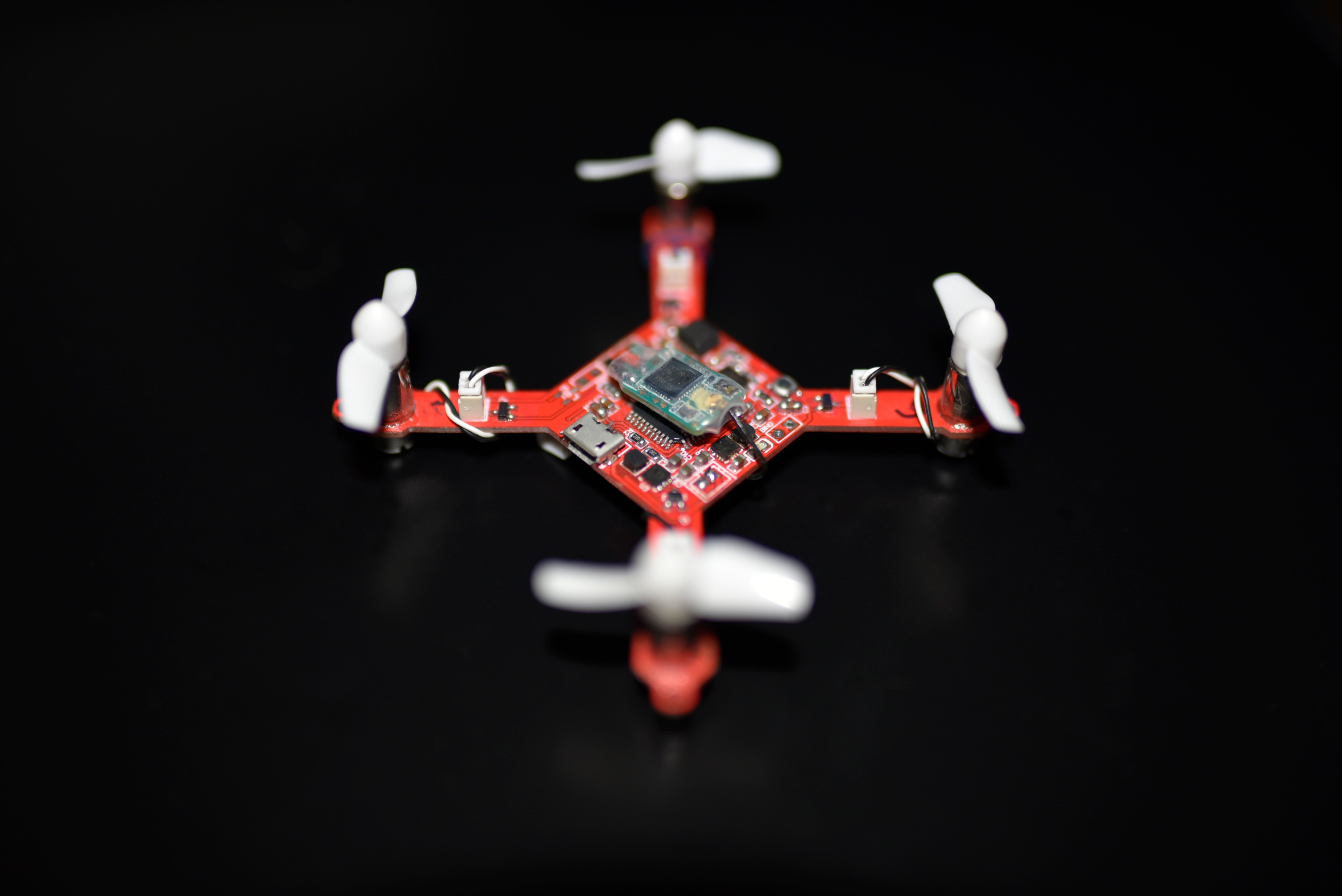
This repository contains the flight controller firmware for my custom designed micro quadcopter. This quadcopter design is based on the atmega32u4 chipset. Find the flight controller design files, here: https://github.com/MichaelD33/AIO-Quadcopter-Design
This program takes orientation data from an inertial measurement unit and input from an external remote in order to fly by adjusting the speed of its motors according to calculations made by the control loop.
Configuration and setup is relatively straight forward. In this early stage of development, the program only supports sBus type receivers and the MPU6050 combined accelerometer and gyroscope. This flight controller could be easily modified to support other RX types by replacing the SBUS.cpp and SBUS.h files with the appropriate library for reading RX data from your receiver. Output this data to the RX.cpp and RX.h files for processing the individual channels (or output to the main program directly from your RX library and remove the built-in RX files)
| Device | MCU Pin Input |
|---|---|
| Frsky XM | RX1 |
| MPU6050 | SDA, SCL |
PWM Motor Outputs: The motor output pins are entirely configurable from within the IDE. Since this flight controller is designed to support brushed motors, the output pins must be PWM capable.
Determining the correct order of the motor outputs can be quite frustrating and may cause the drone to attempt to move in the wrong direction or pitch when intending to roll... When configured correctly, the bottom left motor should correspond with the first field of the pinout array, bottom left with the second, top left with the third, and top right for the fourth (orientation determined according to the direction of the IMU).
For the AIO quadcopter PCB the motor output pins vary for each design, but the proper config is listed in the program main file.
Processor note: this device requires a serial port for the RC input. The receiver is setup under Serial1 for my atmega32u4. This will not work with an atmega328.
Motor Output Diagram:

IMU Offsets: It is important to calibrate the IMU offsets during the initial setup of the quadcopter. This will help compensate for errors in the MPU6050 measurements. These offsets are different for every IMU, so you will need to do this for every individual quadcopter. In the future, I hope to integrate the IMU offset calibration directly into the program; however, for the time being, this is not the case. I recommend this program for obtaining your individual offsets: https://www.i2cdevlib.com/forums/topic/96-arduino-sketch-to-automatically-calculate-mpu6050-offsets/
Add these offsets to the config.h file under the "INERTIAL MEASURMENT UNIT CONFIGURATION" section.
Note: This offset detection program requires the i2cdev library to function. This library is already included with this flight controller repository; however, until the offset feature is implemented directly into the flight controller code, it is necessay to install the library again (directly into your arduino libraries folder), or adjust the IMU.cpp "#include" references to utilize the same library for both the flight controller and the offset detection sketch.
Remote Configuration: The remote configuration is fairly straight-forward if you will be using an s.Bus receiver. Pair the receiver to your remote control and connect it to the Serial1 input on the atmega32u4. Determine the channel endpoints for your remote— technically, these should be 0 —> 2000, but in my case it was 172 -> 1811. You may set this value in the config.h file under the "MINTHROTTLE" and "MAXTHROTTLE" definitions.
(If these parameters are not configured the quadcopter may start the motors even while the throttle is at 0)
The flight control software is built upon the following resources:
- https://github.com/zendes/SBUS
- https://github.com/jrowberg/i2cdevlib
- http://brettbeauregard.com/blog/2011/04/improving-the-beginners-pid-introduction/
This project originally began as a personal challenge in order to improve my embedded programming skills. While I acknowledged the difficulty of programming a device like this, I also was extremely motivated to learn about the ongoing computational processes that take place in an aerial vehicle like a quadcopter. Throughout the process of designing the hardware and writing the code for the flight controller I continually encountered issues with both the physical electronics and my programming. I am still attempting to fix a number of these issues, many of which emerge from flaws in the device's design; however, I have been working on improvements which will hopefully help to mitigate the issues I am currently facing.
The micro scale design of the all-in-one(AIO) frame leads to stability issues because of increased sensitivity to:
- Wind, vibrations, PID tuning, changes in CG, changes in mass, etc.