Adding lots of buttons with an input shift register
As you continue to build panels you may encounter situations where you have more buttons for input than there are pins available on your Arduino. The solution is to use an input shift register like the 74HC165. These allow you to read input from eight buttons while only using three pins on the Arduino. By daisy chaining 74HC165s you can add up to 32 buttons while still only using three Arduino pins.
- A 74HC165 chip
- Eight buttons
- Eight 10kΩ resistors
- A 0.1uF capacitor
The chip is available anywhere you buy electronics, including Amazon, eBay, AliExpress, Tayda Electronics and many other parts suppliers.
Connect the 74HC165 to your Arduino and the buttons as follows:

While the wiring diagram shows an 8-position DIP switch you can use 8 individual tactile buttons instead.
Configure a new device for your Arduino in MobiFlight as follows:
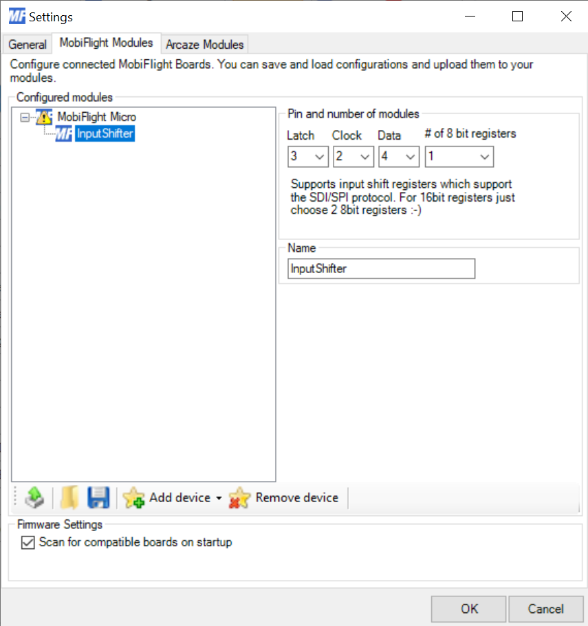
If you choose to use pins other than 2, 3 and 4 here is how you should map the dropdowns in MobiFlight to the pins on the 74HC165:
| MobiFlight Setting | 74HC165 input | 74HC165 pin |
|---|---|---|
| Latch | SH/~LD | 1 |
| Clock | CLK | 2 |
| Data | QH | 9 |
For each input you want to connect to a button configure the input as follows:
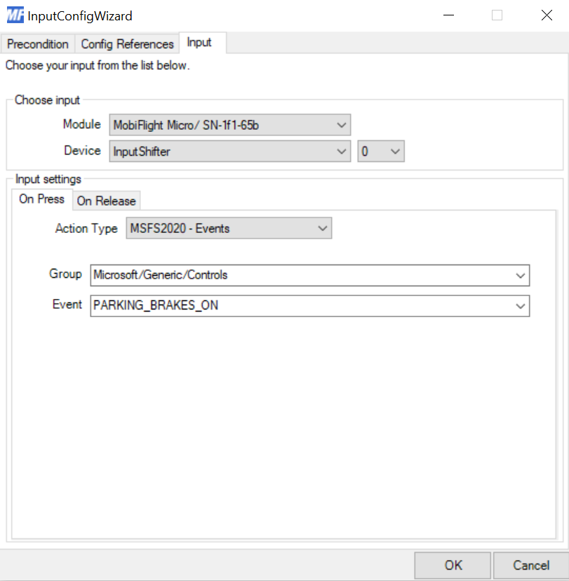
The dropdown next to the device name selects which pin on the 74HC165 is mapped to the input configuration. The mapping is as follows, assuming the chip is wired as illustrated earlier in this tutorial:
| MobiFlight Pin | 74HC165 input | 74HC165 pin |
|---|---|---|
| 0 | A | 11 |
| 1 | B | 12 |
| 2 | C | 13 |
| 3 | D | 14 |
| 4 | E | 3 |
| 5 | F | 4 |
| 6 | G | 5 |
| 7 | H | 6 |
MobiFlight supports up to four 74HC165 chips connected in parallel. When wiring the chips, it is important to wire them so the right most chip in the series is the one connected to the Arduino's data input line. The clock and latch pins are shared across all chips.
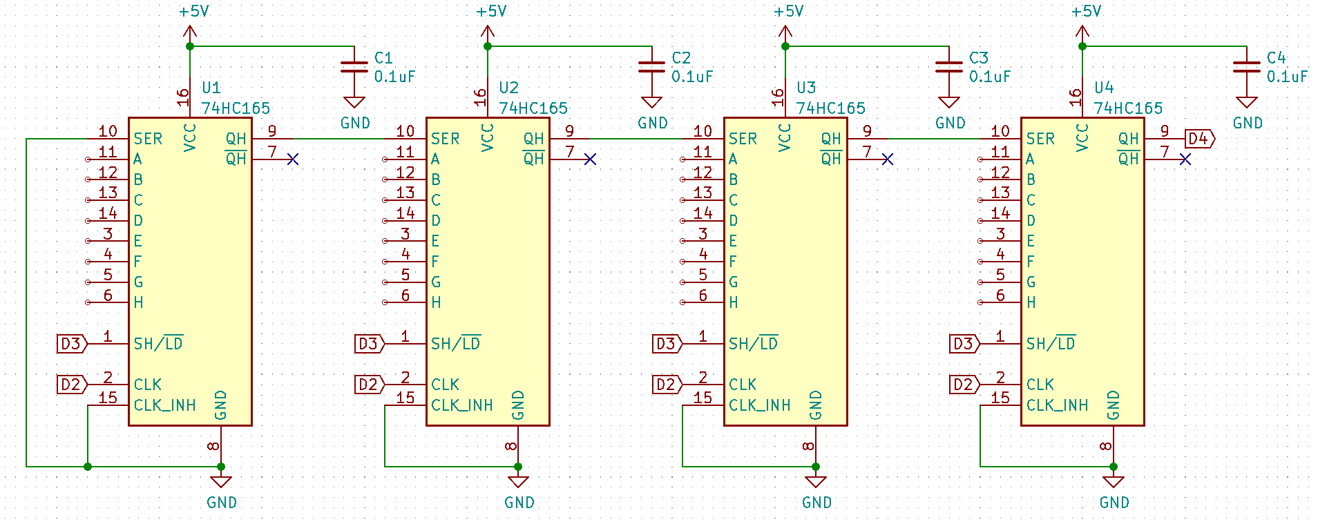
(Buttons and pull-up resistors omitted for clarity)
After wiring the chips in series change the module configuration for the input to specify the number of chips connected in series. The resulting pin numbers in the input configuration dialog are determined by the order the chips are daisy chained together: Pins 0-7 are for the rightmost chip that is directly connected to the Arduino in the above schematic, 8-15 for the second from the right as that is the second in the chain, etc.. Using the debug log feature in Mobiflight will let you also see which number any given switch connected to the shift register is.
- MobiFlight Connector Installation
- Mobiflight Connector BETA version installation
- Modules
- MobiFlight Connector Files Structure
- MobiFlight Connector Uninstall
- Modules Reset to factory default
- Verifying the WASM module installation and locating the MSFS2020 community folder
- Providing logs from MobiFlight
- MobiFlight Connector How does it work
- Mobiflight Connector Main Window
- Flash module with MobiFlight firmware
- Input and Output devices
- Joysticks
- Midi Boards
- Sim Variables (for Output)
- Input Actions
- Merging configuration files
- Disabling specific COM ports
- Examples Output LEDs
- Examples Input Switch
- Example 7 segment display
- Example Servo motor
- Controlling LEDs with an output shift register
- Adding lots of buttons with an input shift register
- Beginner's guide to input multiplexers
- Key Matrix with standard MobiFlight and Multiplexers
- Tutorial Easy Driver and x.27 or x.40 Stepper Motor
- Tutorial for Airbus VS display via 7-Segment LED Module
- Example Analog Input Potentiometer
- Baron G58 Tutorial Gear, Flaps, Mags, ELT Input Output Programming
- Using Mobiflight to control arduino-based 3rd party panels (RealSimGear GNS530)
- How to use a VNH2SP30 DC motor shield with MobiFlight
- Using 3D printer mainboards
- Playing sounds by sending keystrokes to AutoHotKey
- Using the selector knob on a Honeycomb Bravo
- Using an adjustable 12 position switch as a GA starter
- Brightness of LCD displays with I2C
- Using three-position switches
- Transponder with one Rotary
- MSFS2020 RPN Tips and Tricks
- MSFS2020 Using the Custom Input Code Box
- MSFS2020 Install WASM module and Event List
- MSFS2020 How to Create and Use User Defined Lvars
- MSFS2020 How to Create a Blinking LED configuration
- MSFS2020 User Defined WASM Module Events Best Practices
- MSFS2020 Developer Mode, Model Behavior dialog and Console window
- MSFS2020 PMDG 737‐700 List of Events that require use of FSUIPC7
-
MSFS2020 PMDG 737‐700 Calibrate throttle idle and reverse thrust using interpolation (Valkyrie)
- MSFS2020 PMDG 737-700 Chrono unit functions implemented in Mobiflight
- Configuring PMDG 737 Parking Brake Lever Auto-Release with a Servo in Mobiflight
- Using encoder to drive a value back and forth within a given range