Frequency Response with Right Channel as Reference
The in Getting Started section, it was shown how to make a quick frequency response measurement. Using that same technique, let's look at the QA402 in loopback mode. To get there let's do the following:
- File->New
- Disable right trace
- Enable Expo Chirp
- Set Expo Chirp level to 0 dBV (use right click on Expo Chirp button and enter 0 dBV there)
- Change X Log frequency axis to 10 to 25k (use right click on X Log button)
- Set full scale input to 6 dBV
- Set Y Axis to +1 to -1 using Y Axis Preset in Axis Settings
That gives us the following:
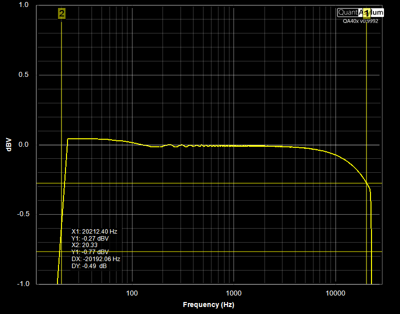
Here we can see that at 20 Hz we're measuring 0.76 dB low, and at 20 kHz we're measuring about 0.27 dB low. What is causing this? The answer is that the frequency response measurement assumes all differences between output and input sweeps are coming from the DUT, and there's no way for the frequency response measurement to know what is being contributed by the following:
- Output DAC filters
- Output DAC anti-alias filters
- ADC input LPF from DC block
- ADC input anti-alias filters
- ADC filters
Now, for most things, the contributions from the ADC and DAC are pretty minor. But if you are trying to understand a digital filter at 20 kHz, then suddenly it becomes difficult to decouple the DAC filter from your own digital filter. What can be done?
The answer is to use the right channel as the reference. This can be specified in the Expo Chirp context menu:
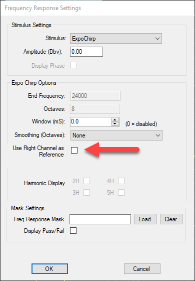
When this is checked, you need the following setup for your DUT:

What we're doing above is we're splitting the Analyzer output and running a version of the output directly into the right channel. This allows the analyzer to "see" what the DAC and ADC contributions look like by themselves.
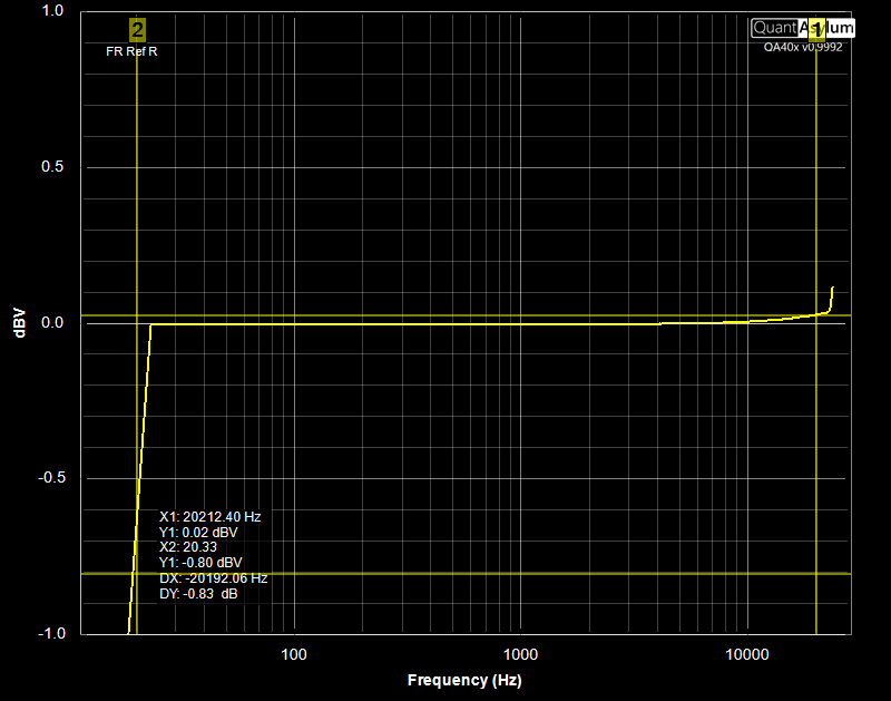
Note that at 20 kHz, our difference from ideal is now just 0.02 Hz. But what about 20 Hz? That is even a little worse. How can that be? The answer is likely due to the input capacitors and the tolerance associated with aluminum capacitors (+/-20%). These are appearing as differences in the DUT.
Make making frequency response measurements, be aware that the 5 elements discussed above will be lumped in with your DUT unless you specify the "right channel as reference" mode of operation. With the right channel as the reference, you will eliminate most of the gross contributions, but you will still see small differences in your left and right channels. The largest source of error in terms of channel-to-channel variation will be the corner of the low-pass filter formed by the aluminum input capacitors.