Speaker Impedance Testing
The QA401 and QA40x software use a very similar SPKR impedance test. The setup schematic for both is shown below:
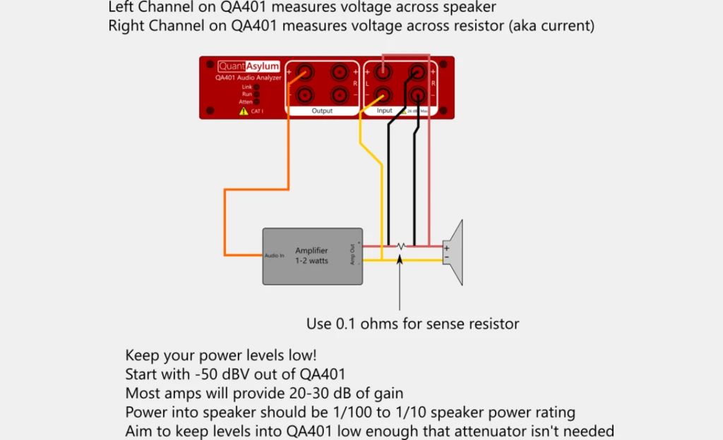
In the diagram above, the left channel is used to measure the voltage across the speaker, and the right channel is used to measure the voltage across a small sense resistor. If you are using a QA460 or QA461 transducer driver, the sense resistor is built in. On the QA460, the sense resistor is 0.1 ohms. On the QA461, the sense resistor is 0.02 ohms, followed by a gain of 50 diff amp with tightly matched resistors that can promise CMRR around 100 dB (which is about 20-35 dB better than the QA460). The benefit of the improved CMRR is that it will extend your ability to measure very small currents, which can be helpful when measuring higher impedance reactive elements.
Before starting the plug-in, you need to ensure you analyzer settings are agreeable with the SPKR Impedance requirements. The following settings are advised, after selection File-> New Settings (to get to a known default state):
Sample Rate Use a 48 kHz sample rate FFT Size Make sure your FFT size is 32K or larger. This will improve the SNR of the measurement. Full Scale Input To keep the SNR high, pick a Full Scale Input that is close to your input signal without clipping. Offsets Make sure your input and output offsets are set to 0 dB. The offsets are specified only in the plug-in because they are applied differently to left and right channels.
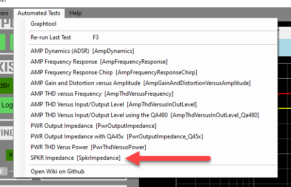
The plug-in can be started from the Automated Tests menu as shown below:
The plug-in settings appear as follows:
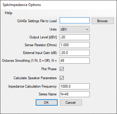
The output level is the level of the exponential chirp that will be generated. Start small to ensure your amp won't damage your speaker. The sense resistor is specific to your test setup. If the sense resistor is too small, then your current measurement on the right channel will be subject to errors. Err on the side of "too big" rather than "too small".
The External Input Gain depends on your setup's attenuation. The QA460 and QA461 have 20 dB of attenuation built in.
Smoothing can be applied by specifying a non-zero value here. The smaller the number, the more smoothing will be applied. Be aware that you can visibly change the shape of your response by picking a number there that is too aggressive. A value of zero applies no smoothing, but if you'd like to evaluate, start with 96, then 48, then 24. The value of 24, for example, will give you 1/24th of an octave smoothing.
Phase can be displayed, and if you wish speaker parameters can be calculated at the specified frequency.
After running the test, the main display should show something similar. Let's focus on what we see at 1 kHz and manually calculate the impedance at that frequency.

At 1 kHz, we can see the speaker voltage (yellow trace) was measured at -20 dBV. But remember, the amp had 20 dB of attenuation. So, the actual value here is 0 dBV, or 1Vrms.
The red trace is the measured voltage across a 1 ohm (effective) resistor. There is no gain associated with the left channel. So, we can see it's about -11 dBV, or about 281 mV across a 1 ohm resistor. That gives 281 mA of current flowing. The speaker thus has 1V across it, with 281 mA flowing, giving an impedance of 3.55 ohms.
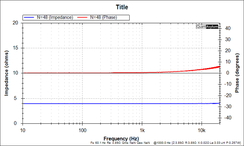
The graph shows as follows:
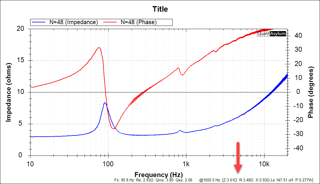
And the computed values agree well with the hand-check.
Let's repeat the process with a four ohm purely resistive load. The result is as expected.
Now let's try again with an open load:
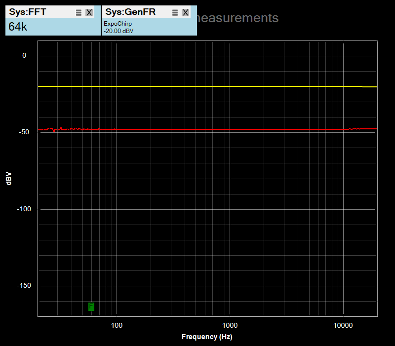
Note the open load (zero current flowing) still yields a sizable reported current. The -48 dBV = 4 mV, which is 4 mA. But we know zero current is flowing, so how can this be? The answer is that the CMRR of the measurement circuit is delivering a non-zero output. And this will be very dependent on your measurement setup. So, the takeaway here is that you need to be aware of the zero-current "floor" and stay far away from that in your measurements. This is easy to avoid for 4 and 8 ohm speakers. But if your aim is graph the impedance of inductors and capacitors, you will need to make sure that the currents flowing are far in excess of the "floor" current you measure.