Inaccurate logo recreation by me.
This repository contains my work-in-progress effort to recreate the Sinclair ZX80.
Changelog (Last updated 21/08/23)
Project Goals
Future Goals
Software
Previous Work
Project Status
Schematics
PCB
Parts List
Case
RF Modulator
Current Issues
Contributing
Licensing
My goal is to recreate the original ZX80 schematic and PCB as accurately as possible in modern software so that replicas can be made via PCB manufacturers such as JLCPCB and PCBWay.
This is both to preserve this piece of computing history and also make it accessible to those of us who don't have $1k+ to spend on an original machine of infamously dubious Sinclair quality.
Obviously this has been done before, but I have yet to find an open-source replica - most other versions, especially the open-source ones, take liberties with the original design (usually to improve it or to make use of modern, easier-to-obtain components).
I also plan to document the differences for the 60Hz (USA) variant, as the changes are primarily the addition or substitution of a small number of components, but this is very poorly documented as of now.
Upon completion of this project, I would like to add a modified version that uses composite video with a built-in backporch, as well as other possibilities such as a 50Hz/60Hz switch.
I would also like to add in the ZX81 modifications as an option for those who wanted an upgraded ZX80 i.e. a ZX81 in a ZX80 case and form factor.
Finally, a future version should be able to be built exclusively with modern components. However, it is important to me that a 1:1 open-source replica is achieved first.
Hopefully, the schematics can be submitted to the awesome Bit Preserve project in the future - a project I recently found that has similar albeit less ambitious goals than my own (primarily that it isn't worried about also replicating the PCBs, just the schematics).
Finally, this is to be the first of (hopefully) many vintage computer replica projects from me, assuming everything goes smoothly.
All my work has been undertaken using KiCad.
The original schematic is ©Sinclair Research.
Grant Searle's redrawn schematic is the basis for this project, and mostly corrects the issues with the original schematic.
However, Grant accidentally wrote MALT instead of HALT for the edge connector.
Also, he did not fix the original schematic's error (or, at least, what I believe to be an error) where both REFSH and RFSH are used for the REFRESH pin, which creates an error in KiCad.
Grant's PCB foils are unfortunately under password protection within an encrypted PDF, so I could not directly import those images.
Instead, I used Martin's modified PCB foils as a template for placing and aligning parts on the PCB.
Martin mentioned two corrections he made but does not elaborate, so I will have to look into this at a future date. These corrections are mentioned in a different article on his website, about halfway down the page.
The first error is apparently that one line is connected to /IORQ instead of /MREQ, which can be fixed by tying pin 19 and 20 of the CPU together.
The other error is that "the 47k resistors that pull up the +5V signals were not connected to +5V" (paraphrasing via Google Translate).
Martin goes on to say that this might not have been the problem and he resolved it by swapping the 47k resistors with 10ks like with the ZX81. This could be a translation issue but I don't understand why this would be necessary if it worked on the original.
Both of these issues need to be investigated further as there should be simple resolutions that match the original board, not some kind of workaround that was never originally required.
It's also worth mentioning that Martin's foils have the right side of Switch 5 connected, whereas Grant's uses Switch 6.
I doubt this makes any functional difference since both are connected anyway, but I'm unsure as to which one is the original. From what I've seen, it's probably Switch 6.
Therefore, both sets of PCB foils are included in this repository as reference material and the copyright belongs to their respective aforementioned owners.
I have also included relatively high quality scans of the original assembly guide (will add the source when I find it again), which has some contradictions to the oft-seen "original" schematic (including the one Grant provides), such as C12 being 100nF instead of 47nF, and the ROM being a 2332 instead of an 8332, and I have chosen to use the differences from this version instead as it appears to make more sense to me.
Finding high-resolution photos of the original PCB is quite difficult, but I have included one that Grant supplied as it has been invaluable (albeit imperfect) to me so far.
The replica keypad was made by using a screenshot from Grant's foils and then tracing it in Adobe Illustrator, so I have included the original Illustrator file in this repository.
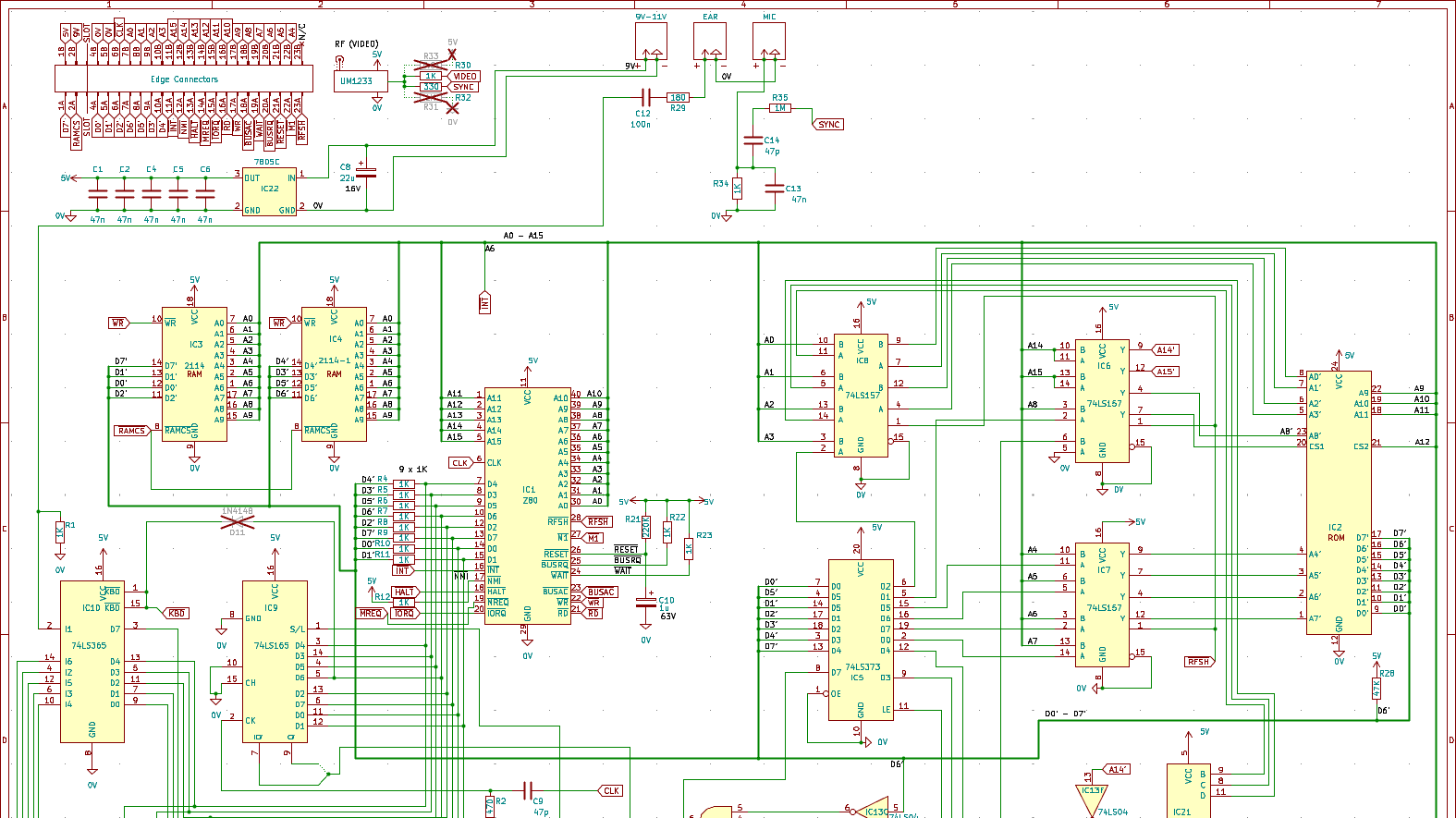
Currently, the schematic is more or less complete though not visually identical to the original.
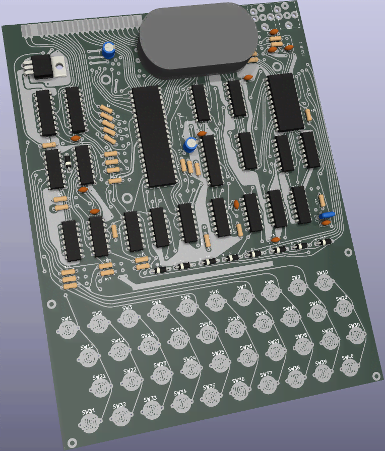
The PCB is at a very early stage, and cannot be completed as the wiring of the schematic does not work perfectly in modern PCB CAD software, so tweaks will have to be made.
As I am a novice with KiCad, I welcome any and all help to make this a workable board.
The traces will be rounded to match the hand-drawn originals on the final version, but any existing traces are simply there for testing purposes and are not final.
Martin's PCB foils are included as a separate PCB file which could in theory be used to print a working replica board (but should not be used, as they are incomplete - the alignment of the two layers isn't perfect, drill holes are not marked, and planes have not been added).
I have created custom footprint and symbol libraries for this project so that any standard parts which needed modification (such as the ICs) to match the original schematic are provided, and to provide parts that wouldn't otherwise exist (such as the Astec UM1233 RF Modulator - more on this later).
Some work still needs to be done, especially for component spacing (and especially the ceramic capacitors), and a lot of rejigging of the silkscreen is still required.
A parts list is available as a CSV, though it is not completed yet (primarily the capacitors and the RAM/ROM ICs).
Grant's parts list has some mistakes which I have corrected (to be detailed at a later date), and I am working on adding information about all the 60Hz-only components to the list as well.
It's worth noting that the listed ceramic crystal resonator may not work - according to Martin, it should be a ceramic discriminator, of which a modern 6.5MHz part doesn't appear to exist.
Unless you can source the original component, I recommend just using the alternate part listed - the 6.5MHz crystal.
A 3D-printable case is available, with Spinetti's version appearing to be the best so far.
The (supposedly) correct rivets can be had from AliExpress.
There are meant to be two sizes of rivets used in the ZX80, with one size having both black and white rivets, whereas the other size only has white rivets.
I will add information in the future once I can test these for myself.
Astec's somewhat ubiquitous UM1233 UHF RF Modulator is an interesting footnote in this project. I have not managed to find any third-party KiCad libraries for this part and so I have recreated it myself to match the original ZX80 schematic.
However, KiCad doesn't handle the logic of this part particularly well, so I've had to implement some work-arounds. If you have a better solution, please feel free to correct it yourself or let me know what can be done.
Also, I cannot 3D model whatsoever, so I picked a similarly-shaped component's 3D model and stretched it into an approximately appropriate shape.
If anyone would like to make a proper 3D model of the modulator, please let me know.
I have original UHF and VHF modulators from Astec which I can measure if need be.
In the interim, I am working on (and almost finished) recreating the UM1233 itself with KiCad so that at least there is a solid point of reference.
These things are getting harder to come by, and in some cases, weren't used outside of European countries (e.g. the New Zealand and possibly Australian ZX81 used the USA VHF modulator from Astec instead, which has the RF jack on the opposite side of the modulator).
Expect a repo for the UM1233 in the near future.
See ERC.rpt for current schematic wiring issues as reported by KiCad's Electrical Rule Checker.
-
What was the original ROM chip used?
One version of the Issue 2 schematic calls it an 8332 (of which I cannot find concrete evidence this even existed), and the other calls it a 2332.
I have seen various other names thrown around, such as the TMS4732 (Texas Instruments 32k) and D2364C (64k, made by NEC I believe - seems likely this was used for the upgrade ROM i.e. the ZX81 ROM, not the original, as it's twice the required size).
Martin suggests that the original ROMs were on an 8332 or TMS4732, with the D2364C indeed used for the ZX80 to ZX81 upgrade. -
Why do many components seem to be of a non-standard size?
Assuming the foil sizing in KiCad is correct (which it seems to be, but I'm not certain), many KiCad footprints don't line up with the vias on the foils.
This may be due to how the original PCB was designed, where they weren't worried about making it an exact match for any one size (e.g. because the legs of components such as diodes and resistors are much longer than necessary anyway, so sizing leeway between each component is fine... until you try to replicate it with modern software). -
Can the power and ground pins for all the ICs that are not marked on the original schematic be hidden (instead of sitting off the bottom of the page) in the KiCad schematic without upsetting KiCad's Electrical Rules Checker?
The answer is "yes" but I don't entirely understand it at this point. More reading required. -
How can the address lines be connected like the original schematic without causing problems in KiCad?
Kind of a major issue - this ties most of the address lines together, which isn't really correct (look at the rear PCB foil for a good example of how they're meant to linked). This throws all sorts of errors in KiCad, including making the PCB layout an inaccurate mess.The answer is using buses. KiCad isn't smart enough to figure out you're creating a bus when using regular wires - you have to explicitly draw a bus connection instead.
It's clever once you figure it out, but it would be nice if the bus-to-wire connections could be drawn at 90° instead of 45° to match the original schematic. -
Is~{SYNC}used anywhere outside of IC19 pin 6?
~{SYNC}is connected to the RF modulator where the schematic is labelled0V(GND). -
Why the discrepancy between schematics (especially since both are for Issue 2)?
-
How should pins with multiple values (e.g. RF modulator's
VIDEOand5Vor~{SYNC}and0V) be wired in the schematic? -
What is the correct value for TR1?
Supposedly, it should be a ZTX329. -
Why is a net label required forA8'to connect properly on IC2 (ROM) pin 23 when no other address lines appear to have this issue?
It's there on the schematic but is on the IC6 side (pin 4) instead. The ZX80 schematic doesn't have unique pin names for most ICs hence the need to define with with a label. -
What are the missing values for the 60Hz parts?
There are photos floating around of 60Hz versions so this could be reverse-engineered from those, as I have done for some of the known values (check the parts list CSV).
If I think of more unknowns (at least to me), I'll add them later.
Feel free to open an issue to contribute your own if you think it's crucial.
The further I get with this project, the more daunting it seems, as there is a ton of work left to do, and replicating something not designed in modern software with the limitations of modern software is surprisingly difficult.
Therefore, if you would like to help, please feel free to open an issue if you find an obvious correction needs to be made (please don't do this for WIP parts unless you see a fatal error - they're obviously a work-in-progress for a reason), or make a pull request with any edits.
I will have to add this properly when I get more time in the future.
In short:
- All work not done by me is copyright its respective owners, where the original licenses apply.
- All work done by me is copyright Gare Ltd. but completely free for non-commercial use of any kind with attribution (but it'd be really cool if you contributed to this project instead of just making your own version).
- My ZX80 logo recreation was made using Wikipedia's SVG Sinclair logo as a base.


