VGA demo on bluepill (using STM32F103 microcontroller)
There are 4 demos:
- Displaying color image (taken from http://www.worldofspectrum.org/pub/sinclair/screens/load/b/scr/BubbleBobble.scr)
- Text typing and moving cursor (font is taken from http://caxapa.ru/149446.html)
- Drawing (taken from https://github.com/Avamander/arduino-tvout/blob/master/examples/DemoNTSC/DemoNTSC.pde)
- Game (taken from http://http.debian.net/debian/pool/main/x/xonix/xonix_1.4.orig.tar.gz)

Video
My idea of “fun” maybe odd, but here it is. This is a demo that displays a color VGA video with resolution of 256x192 and 64 colors without any specialized video hardware on a tiny STM32F103 board that can run only up to 72 MHz and has only 20 KB of RAM.
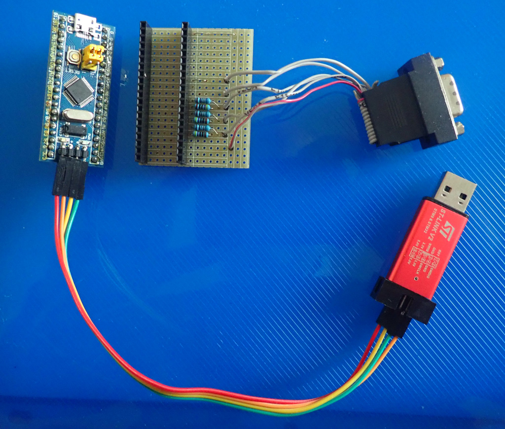
If you want to try my project, this is the only part that you need.
| Hardware | Qty |
|---|---|
| "blue pill" STM32F103C8 board | 1 |
| Resistors 470 Ohm | 3 |
| Resistors 680 Ohm | 3 |
| Breadboard | 1 |
| VGA connector (I used one from the old video card) | 1 |
| Jumper wires | 15 |
| ST-Link v2 or clone | 1 |
Software (under Windows): Install Visual Studio Code, then PlatformIO plug-in.
How to connect wires:
| PIN | Description | Connect To | Output |
|---|---|---|---|
| PA0 | Red 1 | Resistor 470 Ohm | VGA red (1) |
| PA1 | Red 2 | Resistor 680 Ohm | VGA red (1) |
| PA2 | Green 1 | Resistor 470 Ohm | VGA green (2) |
| PA3 | Green 2 | Resistor 680 Ohm | VGA green (2) |
| PA4 | Blue 1 | Resistor 470 Ohm | VGA blue (3) |
| PA5 | Blue 2 | Resistor 680 Ohm | VGA blue (3) |
| PB0 | HSync | VGA HSync (13) | |
| PB6 | VSync | VGA VSync (14) | |
| G | Ground | VGA Ground (5,6,7,8,10) |
To generate VGA signal I am using 3 timers. TIM2 is used as a "shock absorber" (for a detailed description of this brilliant idea, see A Glitch in the Matrix). TIM3 is used to generate HSync signal on PB0 using PWM and also to generate interrupt TIM3_IRQHandler, which calls DoDraw, which outputs pixels. TIM4 is used to generate VSync signal on PB6 using PWM and also to generate interrupt TIM4_IRQHandler, which sets a flag that indicates that we can draw on screen.
USB serial is used in this demo. I decreased the priority of the USB interrupt so it wouldn’t interfere with the VGA output. You can connect using VT100 terminal, such as Tera Term, to use the demo.
Also, since the VGA output is very tight, I disabled SysTick. To implement delay, I am using RTC. It is actually not trivial to read time from the RTC. The reason is that we need to read 3 values, and there’s no way to do it atomically. For the solution, see the implementation of the Vga::millis which I took from Reading STM32F1 real-time clock.
This project was born some time ago when I first installed a great TVOut library on my Arduino Mega. I was really impressed with the fact that so small board (it is based on a tiny 16 MHz 8-bit processor) can display a video with reasonable quality.
I started to look at similar projects and found a "Glitch" demo, which is using more powerful, but still tiny, 32-bit processor. The “Glitch” was an inspiration for this project. I decided to get something in between and chose a "blue pill", which is using a 32-bit STM32F103 microcontroller, similar to the one in “Glitch” demo, but cheaper and less powerful (and as a bonus, it supports Arduino).
The STM32F103 board that I chose can run only up to 72 MHz and has only 20 KB of RAM, compared to 168 MHz and 192 KB of RAM that “Glitch” demo is using, however I was hoping to use code very similar to Cliff’s. I decided to support a resolution of Sinclair ZX Spectrum computers. By using “color attributes” (the colors are defined for 8x8 blocks of pixels, not for each pixel), the whole video memory can fit into only 7 KB of RAM. In this demo I am using 2-byte attributes instead of 1-byte attributes and takes approximately 7.7 KB. The reason is to simplify assembly code that pushes out the pixels.
However, I was disappointed that even though the DMA is supported, it apparently can’t run fast enough for my goal. This article explains this fact in detail. So, the only option left was to use the approach similar to TVOut library. Please note, that it is possible to use DMA+SPI to create “green and white” VGA output (see great Artekit demo).
After some time learning ARM assembler language I had an Arduino code that could display 256x192 with 64 colors; however I was getting a weird “zigzag” effect which I cannot explain even now. After struggling for some time to figure out the reason for that effect, I gave up. It was time to try to get closer to the hardware. I decided to switch to the STM32Cube library. Originally, I thought that it will take a very short time. After all, Arduino is not really an operating system, how hard it can be? After rewriting my demo using HAL, I was hoping that it will run very soon. No, it didn’t.
Since I don’t have oscilloscope or logical analyzer, I had no idea why nothing was shown on the screen. So, I had to learn what Arduino was doing for me at the start, which is actually quite a bit. After some time I realized that the reason was that my processor was running at 8 MHz, not 72! What a surprise! If you are interested, the code that switches to 72 MHz and does some other things, like initializing USB clock at 48 MHz is SystemClock_Config (in startup.c).