0. Overview
This project provides:
- a practical means of harnessing a rich array of the most important flight telemetry data from the Ardupilot flight controller
- a way to convert this telemetry into the FrSky SmartPort protocol allowing the X series receiver to send it down to the Taranis radio
- a custom telemetry screen allowing the telemetry to be displayed on the Taranis.
- as well as a the screen providing visual information it also provides audio alerts/information to the pilot.
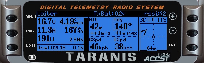
The custom Telemetry screen for both Copter and Plane versions of the Ardupilot firmware looks like this:
Pressing the MENU button at any time whilst in this screen will display the configuration screen:
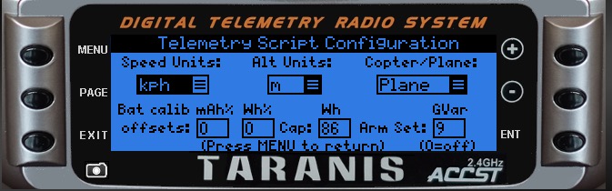
This configuration screen provides:
- speed and altitude unit display options:
- Speed: m/s, kph, mph, kts
- Altitude: m, ft (also m/s, f/s for climb rate)
- choose whether the model is a Copter or Plane (this will effect the flight modes display and calls)
- offset calibration values for mAh and Wh readings (allows calibration of the values on the main screen, see here for more info on calculating this)
- battery capacity (in Wh) will scale the battery meter and set the Wh alarm
- Arm Set GVar: This allows you to select a Global variable which will be set to its max value upon arming the model. This can be used in mixes or custom switches as desired - one application is assigning it to a channel in order to switch on PWM controlled lights when armed (such as a strobe/beacon).
(Changes to these options are saved to the SD card for each model under folder /SCRIPTS/TELEMETRY/DATA)
Pressing MENU again will return to the main telemetry screen.
Voltage/Current monitoring options:
- By default, the project will work in combination with the FrSky FLVSS LiPo monitor (which provides individual cell voltages from the connected LiPo balance connector). Its even possible to utilise two separate FLVSS sensors for a dual battery setup, and configure the telemetry to display the voltage of the most depleted cell on the telemetry screen.
- Alternatively, for more adventurous pilots the project even includes details and support for a DIY battery cell monitoring solution - known as the 'LiPo Single Cell Monitor'.
- A third option is to use no battery cell monitor at all, but instead have the cell values estimated in order for the cell voltage value to be displayed in the telemetry sceeen. This is the preferred option where using a ground based Teensy board (such as is the case when using Ultimate LRS).
- Finally, the project also provides a means to integrate alongside the FrSky FAS (current/voltage) sensors available for SmartPort (with a minor code change to disable Mavlink voltage data), for those who prefer to use a FAS device instead of an APM power module.
LED Options:
Several options have been developed for allowing the control of strips of addressable LEDs which can be placed on the model to provide customisable visual flight information.
##How this is possible:
All of this is made possible by adding a small Arduino project board called a "Teensy" between the APM/PixHawk and the FrSky X series receiver - this device runs a custom protocol translator code provided by this project. Running the code, the teensy listens to several different streams of Mavlink telemetry data produced by Ardupilot, and chooses just the data it requires, re-packaging this into FrSky S.Port compatible data, feeding this into the FrSky SmartPort system. On the Taranis radio this data is presented in the form of several different FrSky telemetry sensors. The telemetry screen you see examples of above and below is provided to make sense of all this data, presenting it in a more readable form on the Taranis screen.
Supported Hardware Currently we only support Teensy 3.0, 3.1, 3.2, LC hardware.
##Under the hood (for those who want to delve a little deeper)
The code which runs on the Teensy board does have several options for user configuration. This allows the board to be used in several different scernarios. It is therefore necessary to have the Arduino IDE (with various extensions and libraries) installed on your PC/Mac in order to configure, and download the code to the Teensy board. This installation is described in the following pages.
The code running on the Teensy uses custom modified open source FrSky telemetry libraries in order to emulate various physical FrSky SmartPort telemetry sensors (and add a few new ones). It is possible of course to configure a model build to use only physical FrSky telemetry sensors - which would be daisy chained together and finally fed into the smartPort of an X series FrSky receiver. In this physical configuration, each of the FrSky sensors would have a unique hard coded ID allowing each to be presented to the Taranis individually on the smartPort bus. Comparing this with the Teensy solution, the code running on the Teensy simply emulates many seperate FrSky telemetry sensors, all of which are presented by the Teensy over a single physical smartPort connection of a X series FrSky receiver. It is possible to configure the code (before it is written to the Teensy) to disable some of the emulated telemetry sensors it provides, in order to allow a configuration which allows the teensy to work in combination with one or more physical FrSky telemetry sensors.
Additionally, further configuration of the teensy code allows it to be used in a 'Ultimate LRS' ground station configuration. The ULRS system is rather special in that it provides the ability to send down the Mavlink data to the ULRS transmitter on the ground. So using this configuration we are able to install the teensy, connecting it to this Tx accessible Mavlink feed, and connecting the smartPort output from the teensy either directly into the back of a Taranis radio (or alternatively into a FrSky X4R receiver where this is part of a ground station repeater unit).
These different configurations will be discussed in the following pages.
Additionally the script provides several different audio alerts/messages to keep the pilot informed without even needing to look down at the screen - this allows the pilot to concentrate on flying the craft instead.
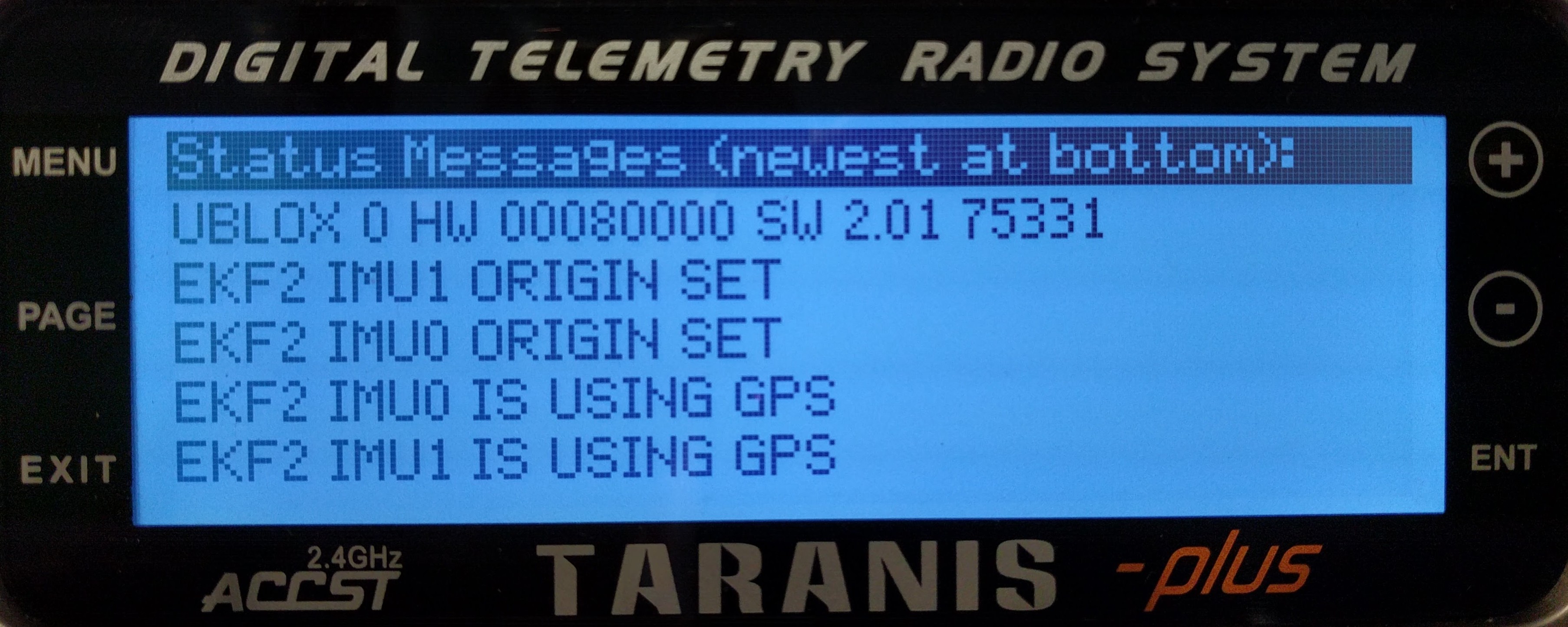
A second telemetry script is also provided with the project (called textmsg.lua) which allows Ardupilot status messages to be dispolayed on the Taranis screen:
The telemetry sensor information provided by the Teensy board to the Taranis radio is detailed in section 1.2.1 - Telemetry Value Overview
##A more detailed explanation of the main telemetry screen layout:
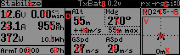
| Field | Description |
|---|---|
| A | Current Flight Mode Active as reported by the Flight Controller. If blinking the vehicle is not Armed. |
| B | Radio Transmitter Battery Voltage. |
| C | RSSI value (this can either be 'rssi:' = from FrSky Tx/Rx, or rx-rssi: = from Mavlink) |
| D | Wh Gauge. Display Battery capacity left. Need to enter battery capacity in Wh in the telemetry screen configuration page for this to display correctly. Setting Wh capacity to 0 disables this feature. |
| E | Reported Flight Battery Voltage from MavLink or if configued for LiPo Single Cell monitor, this will display the voltage read ad the teensy from the balance connector. See Section 2.1 for details. |
| F | Lipo Cell minimum. this simple display lowest cell from your lipo |
| G | Reported Flight Battery Current. |
| H | battery consumption in mAh, offset adjustable from within the telemetry screen configuration page |
| I | Actual power output in Watts (VxA) |
| J | power consumption in Wh, offset adjustable from within the telemetry screen configuration page |
| K | Heading in degrees |
| L | Baro-Altitude (relative to launch position). Units can be set in the telemetry screen configuration page |
| M | Climb/Descent rate. Units selected as per Baro-Altitude (L above, but reflects as m/s or f/s). |
| N | Maximum reached Altitude. Units selected as per Baro-Altitude (L above). |
| O | Ground Speed - units can be set in the telemetry screen configuration page |
| P | Air Speed (if an airspeed sensor is fitted then this will be used, otherwise estimated airspeed is displayed). Units selected as per Ground Speed (O above). |
| Q | Armed Time Timer - Starts and stops when the Vehicle is armed/disarmed |
| R | Operating Hours Counter, shows the model operating hours in armed status. As an option coupled with the service Lua script |
| S | GPS Indicator, 3D, 2D or no status |
| T | HDop indicator. Blinks when over 2 |
| U | Number of reported satellites |
| V | Radar |
| W | Vehicle Arrow can move and rotate within the radar frame. This displays position relative to home (signified by the center of the frame) and heading relative to home (signified by the arrow direction). |
| X | Distance to home (Distance to the point the Taranis was armed) Units selected as per Baro-Altitude (L above). |