2.5. Ultimate LRS Support
ULRS is a frequency-hopping long range DIY RC solution, designed to provide long range RC control and 2 way telemetry using 1W transmitter and receiver modules over UHF frequencies.
The Official ULRS website can be found here
The RC Groups ULRS forum post can be found here
This solution provides a 2-way 19.2k baud serial link between the Tx and Rx. This allows the Mavlink data stream from a telemetry port on the pixhawk to be fed down to the ground station via serial ports on both the ULRS Rx and Tx boards. Having this mavlink telemetry accessible from the transmitter allows us several interesting options for ground station telemetry. Not only does this allow us to connect a bluetooth module which provides mavlink access to our favourite ground station software (such as Mission Planner), but it also provides a means for us to connect our Teensy solution to this serial Mavlink connection at the ground-side (instead of the traditional installation where it would be installed in the plane/copter). There are two methods of installing the Teensy at the ground-side RC connection:
- In a repeater station
In this case, the ULRS Transmitter board would be installed in a standalone project box, and the RC inputs to it would come from the CPPM output of a FrSky X4R Receiver, also installed in the project box. The X4R is chosen for this solution specifically as the newer firmware allows an 8 channel CPPM output which feeds into the PPM input of the ULRS Tx nicely. The input to the X4R is received in the usual way from the Taranis radio over 2.4GHz. The Teensy board in this configuration would take the Mavlink feed from the serial port of the ULRS Transmitter, and feed the S.Port output into the S.Port input of the X4R - passing this down to the Taranis in the usual way. The project box would of course require its own power supply (such as a LiPo battery with 5v BEC to provide power to both Rx and Tx units, also to power the Teensy, and a bluetooth serial module (should one be connected for ground station connection).
In this instance, the X4R Rx 'polls' for telemetry sensors provided by the Teensy in the native FrSky way, so no special configuration is required within the Teensy code.
- Directly into the Taranis
In this case The ULRS Transmitter board would be installed at the back of the Taranis radio directly, and connected via the module bay port, which provides a 16 channel CPPM output directly to ULRS (plus power). In this configuration, the Teensy board would be connected to the serial mavlink output of the ULRS Tx board, and the Teensy S.Port output would be connected to the S.Port pin within the Taranis module bay. Special consideration would have to be given to powering each of these units at the correct voltage.
In this instance, there is no FrSky Rx to do the S.Port telemetry sensor polling (as the S.Port output of the Teensy is connected directly to the Taranis), so in order to have the S.Port sensors 'polled', the Teensy code contains an optional 'polling' addon which can be enabled to provide this function (in place of that usually provided y the S.Port Rx). To enable the polling add-on, un comment the line in the addon's section of MavLink_FrSkySPort.ino so it reads: #define POLLING_ENABLED
Here are some images of a typical ULRS DIY built Transmitter module:
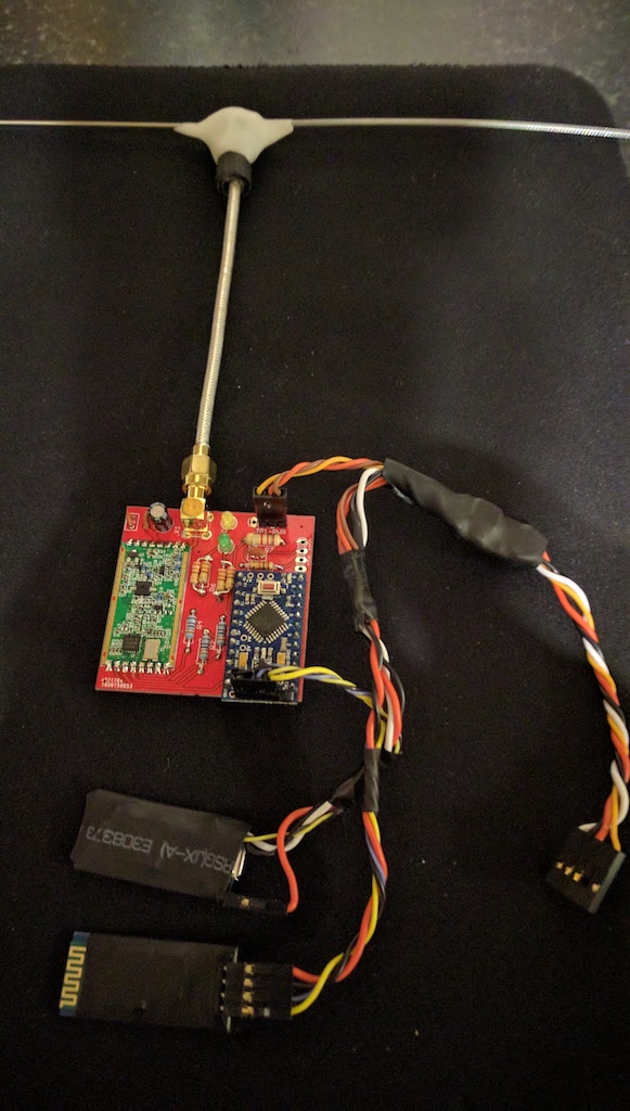
The components connected - ULRS Mini (sponge) board, with BT adapter and Teensy 3.2
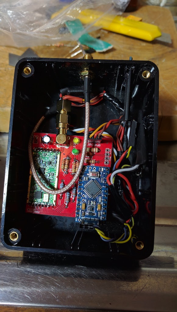
The same components installed in a project box with JR module fixed to rear for Taranis connection
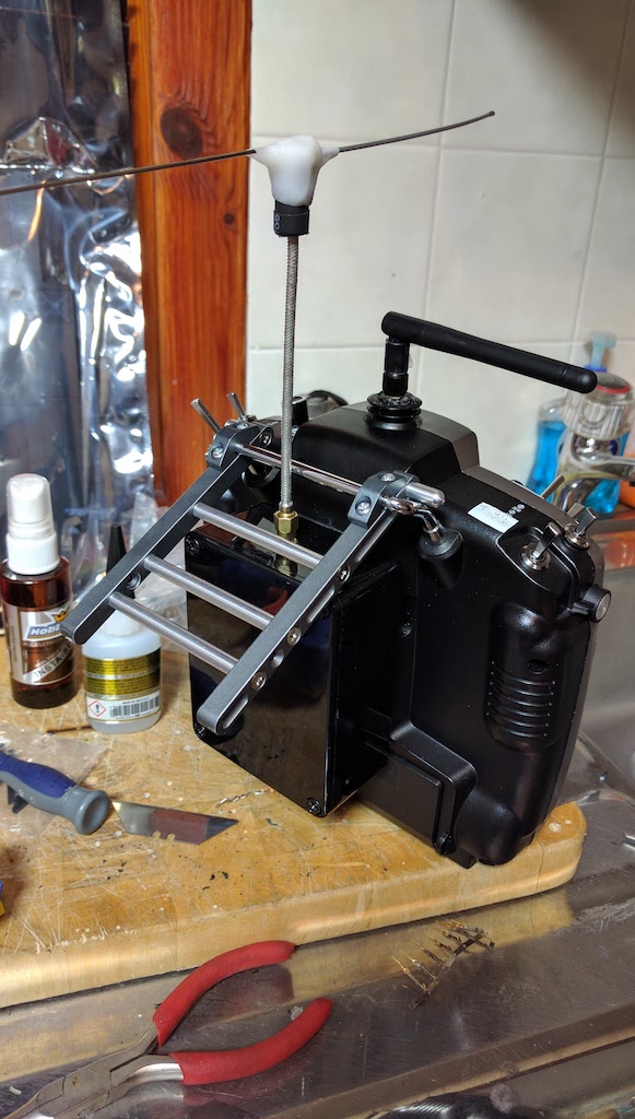
Finished solution fitted to Taranis
RSSI Telemetry for ULRS
When using any LRS system, the RSSI data of the UHF radio link is often provided in one (or both) of the following ways:
- by a dedicated PWM pin provided on the Rx in the model - ULRS provides a dedicated pin on most ofits ULRS Mini board designs, such that when they are configured as a Rx, the RSSI value of the link is provided in PWM form on this pin. In tests, I have found that providing an accurate RSSI reading using this PWM method can be quite challenging, and instead prefer to use method 2 below instead for a much more reliable RSSI source. For the pixhawk to read the RSSI value from this pin, it must first be converted from PWM format to a smooth analog voltage level (3.3v based) by constructing a suitable LP filter/DAC for which the analog output should be connected to the SB connection of the Pixhawk. Ardupilot must then be configured to accept this analog RSSI data on pin 103 (the SB pin), using parameters similar to the following:
- RSSI_TYPE: 1
- RSSI_ANA_PIN: 103
- RSSI_PIN_LOW: 0 (should be adjusted to reflect the low RSSI voltage value from the LC filter)
- RSSI_PIN_HIGH: 3.3 (should be adjusted to reflect the high RSSI voltage value from the LC filter)
- by assigning the RSSI data to an RC channel within the configuration software for the RC system. In ULRS, you can assign the RSSI value to any of the 16 available channels from within the CC application. Once assigned, Ardupilot must then be configured to use this RC channel as the source for its rx-rssi value, by configuring the following parameters:
- RSSI_TYPE: 2
- RSSI_CHANNEL: (enter the channel number which you assigned the RSSI to in the LRS configuration)
- RSSI_CHAN_LOW: 1000 (the pwm value for low RSSI reading. In ULRS, this should be 1000)
- RSSI_CHAN_HIGH: 2000 (the pwm value for high RSSI reading. In ULRS, this should be 2000)
Either of the above configurations should provide a value for rx-rssi in Mission Planner. This RSSI value is also made available in Ardupilot's Mavlink telemetry stream, and it is this telemetry value which the Teensy can be configured to make available to our Taranis telemetry screen - discussed in the following section. For more info on RSSI parameter configuration in Ardupilot, please refer to this link
In order to have the Teensy provide this mavlink RSSI data to the Taranis, un-comment the line in the addon's section of MavLink_FrSkySPort.ino so it reads: #define USE_MAV_RSSI
This will feed the RSSI value (in %) to the A3 sensor (replacing the Roll Angle value usually sent to A3, and will replace the A4 value with 0). The LUA screen will automatically recognise that A4 is set to 0 and because of this, display rx-rssi: % in the top-bar. The value sent on A3 will be used as the source for the rx-rssi value displayed here.
Here is an example of the Telemetry solution provided by the above depicted ULRS setup:
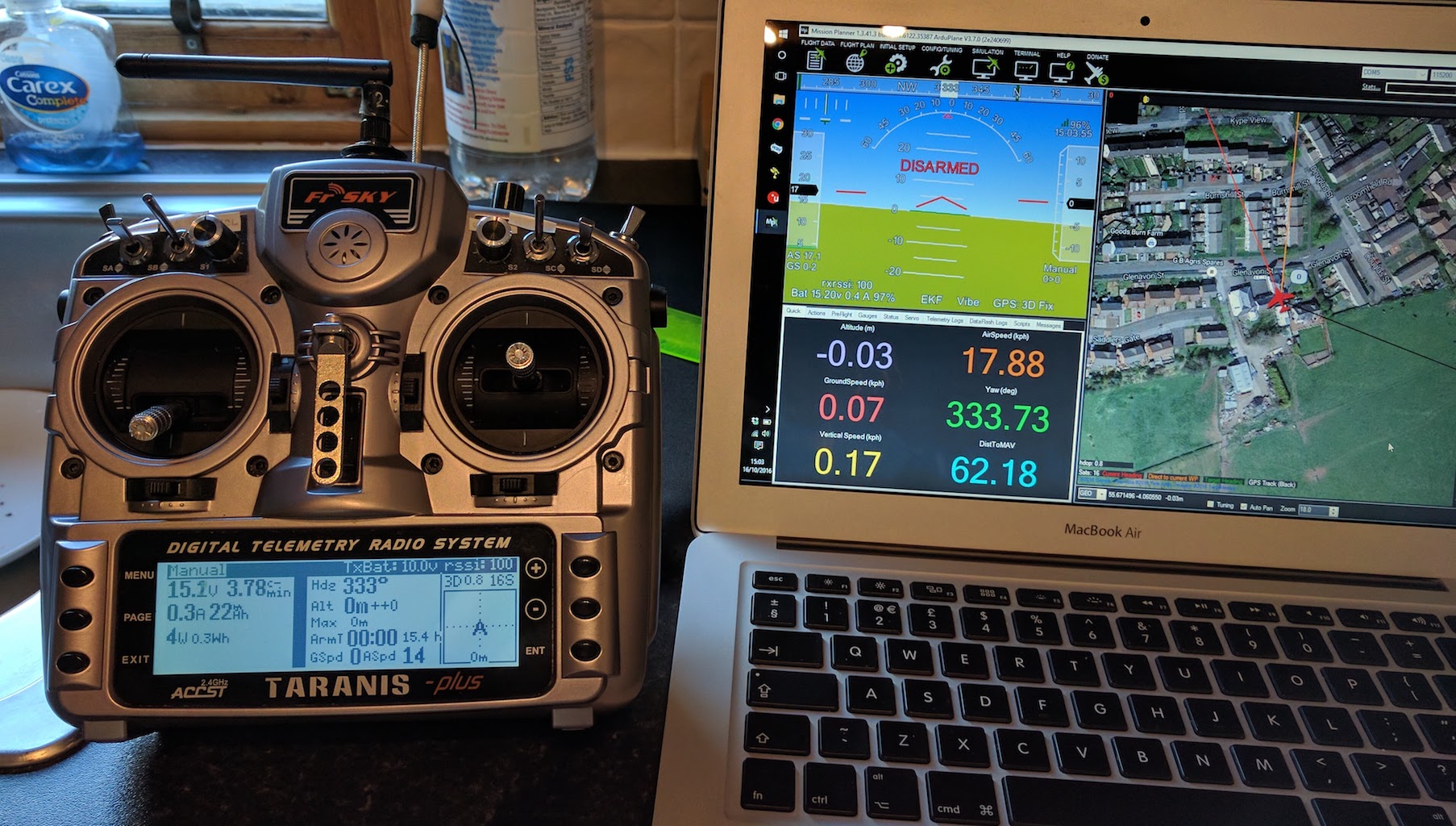
The LUA screen on the Taranis shows the regular telemetry but in this configuration it is coming from the teensy installed inside the ULRS Tx enclosure (please ignore the older version of telemetry screen shown in the above image). Mission Planner is connected over Bluetooth to the BT adapter also connected to the ULRS Tx mavlink feed.