Example_FSG
If you do not have a CCU (FSG) or your CCU is defective, it is also possible to mimic/replace the CCU behaviour via piTelex in a special mode, so that you can connect a current loop teleprinter directly to piTelex and use it with full CCU functionality.
-
The relay for switching the loop polarity is replaced by a power relay switching the mains power for the teletype (230 volts).
-
Furthermore, three additional pushbuttons, connected from the RPi's GPIO to GND, take over the functionality of
AT,STandLTbuttons of the CCU. -
The state of the CCU can be indicated via the LEDs
LED_A(line active),LED_WB(ready to dial, "WählBereit"),LED_LT(local mode), which are connected from RPi GPIO pins to GND with a series resistor of 1kOhm. -
ALternatively you may concentrate all that to a minimalistic single pushbutton
1Twhich will cycle through the states, and one dual color LEDLED_status_R(red terminal) andLED_status_G(green terminal). -
If you want to dial via number switch, connect the nsi/nsr contacts between a pin
pin_number_switchof the RPi and Ground (0V).
For the current loop power supply, a voltage of about 24V= will be sufficient, because we only have to feed the TTY's receiver coil, no CCU in line.
telex.json has to reflect the missing CCU, and must configure piTelex for this special mode.
This is done by modifying the RPiTTY device enries a bit and, most important, activating the RPiCtrl device which allows to specify the pushbuttons and LEDs mentioned above. For Details see SW_DevRPiCtrl
Here piTelex is installed in the gutted housing of a defective original CCU unit. Number switch and buttons are still used to control piTelex. This example uses the same piTelex hardware as the example "TW39 Raspberry Pi" except using a SSR for power switching.


The FL/A connector is soldered on the Raspberry Pi Zero W to connect an external antenna - a metal case is not WLAN-friendly.
Two industrial power supplies are added to source 5 volt for the RPi and 24 volt for the current loop.
Note: For a teletype without a real control device (FSG) in line a loop voltage is adequate.
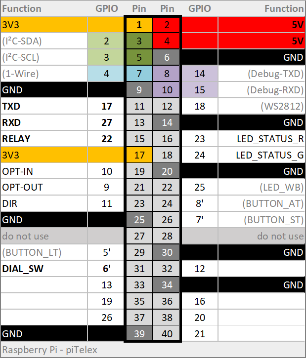
- TXD = Pin 11 (GPIO 17)
- RXD = Pin 13 (GPIO 27)
- Number Switch = Pin 31 (GPIO 6)
- AT-Button = Pin 24 (GPIO 8)
- ST-Button = Pin 26 (GPIO 7)
- Show Sign = Pin 15 (GPIO 22) over NPN-transistor to 24 volts
- GND = Pin 6 and/or 9, 14, 20, 25, 30, 34, 39
- 5V = Pin 2 or 4
Note: All buttons/switches connected to GND
Note: These are the default pins. Other combinations can be set in
telex.jsonfile.

This is a fully DYI solution with a custom circuit layout. The ULN driver IC has been replaced by a few cheap BC337 and some resistors. TIP50 isn't really needed, transistor types with lower U_CEmax values will do (we just have 25V as loop voltage...).
Power supply uses two industrial hybrid modules, one provides 5V for the logic and the other one delivers 24V loop voltage. This solution has significantly less power loss and stays therefore cooler than a linear 7805 to reduce 24V to 5V but is in fact a bit more expensive. There are many ways to Rome...
The number switch is taken from an old phone. NSI and NSR are used to form the dial impulses, NSA is unused.
The pushbuttons contain built in LEDs which are assigned as follows:
| button | LED |
|---|---|
AT |
LED_WB |
ST |
LED_A |
LT |
LED_LT |


(used pins are not always standard...)
    "RPiTTY": {
      "type": "RPiTTY",
      "enable": true,
      "pin_txd": 27,
      "pin_rxd": 17,
      "inv_rxd": false,
      "pin_relay": 6,
      "inv_relay": false,
      "pin_number_switch": -1, # we use the definition in RPiCtrl, therefore deactivate it here
      "baudrate": 50,
      "coding": 0,
      "loopback": true,
      "use_observe_line": false
    },
    "RPiCtrl": {
      "type": "RPiCtrl",
      "enable": true,
      "pin_number_switch": 5,
      "inv_number_switch": false,
      "pin_button_1T": 0, # we use explicit AT,ST,LT buttons
      "pin_button_AT": 25,
      "pin_button_ST": 7,
      "pin_button_LT": 8,
      "pin_LED_A": 23,
      "pin_LED_WB": 24,
      "pin_LED_LT": 16,
      "pin_LED_status_R": 0, # unused
      "pin_LED_status_G": 0, # unused
    },
- Local use
-
i-Telex
- tbd
- Advanced Topics
- Acccess SD-Card from Windows
- Show INET Address in Console
- Off-button for RPi
- Multiple piTelex Instances
- Mail notification on new telex
- Circumvent DS-Lite restrictions
-
TW39 (current loop)
-
ED1000 (FSK modulation)
-
V.10 (TeKaDe FS200, FS220)
-
SEU-M-board based
- with Austrian AGT (Ö-AGT, current loop)
- inside LO2000, LO2001, LO3000 (SEU-B replace)