##Install the Go-Kart-Control software
Download and unzip the ZIP archive containing all executables and also the source code:
https://github.com/gerdb/go-kart-control/archive/master.zip
On a windows system just start the executable Go-Kart-Control.exe in /install/win32 or win64
On a Mac or Linux start the java JAR archive in install/all with java - jar go-kart-control.jar.
Don't forget to set the correct serial port in settings.txt.
Java must be installed: https://www.java.com/de/download/
##Translation
You can translate the application.
Open the lang/messages.pot file and translate it with http://poedit.net/
Save the messages_LANGUAGE_CODE.po file in the lang folder of your program.
Set the local code in settings.txt, if you don't want to use the system settings.
##Arduino software
If it's a new AVR, program it with the Arduino bootloader. For example with AVRDUDE:
avrdude -pm32u4 -cstk500 -P/dev/ttyUSB0 -e
avrdude -pm32u4 -cstk500 -P/dev/ttyUSB0 -v -e -U lfuse:w:0xff:m -U hfuse:w:0xd8:m -U efuse:w:0xcb:m
avrdude -pm32u4 -cstk500 -P/dev/ttyUSB0 -v -e -U flash:w:Caterina-Micro.hex -U lock:w:0x2F:m
The Arduino project file is: arduino/go_kart_panel/go_kart_panel.ino
##Hardware setup
The PCB can be assembles in 2 variants: As a master module or as a panel module.
The master module is connected to the PC.
The panel module has a display.
The differences between both electronics are marked here:
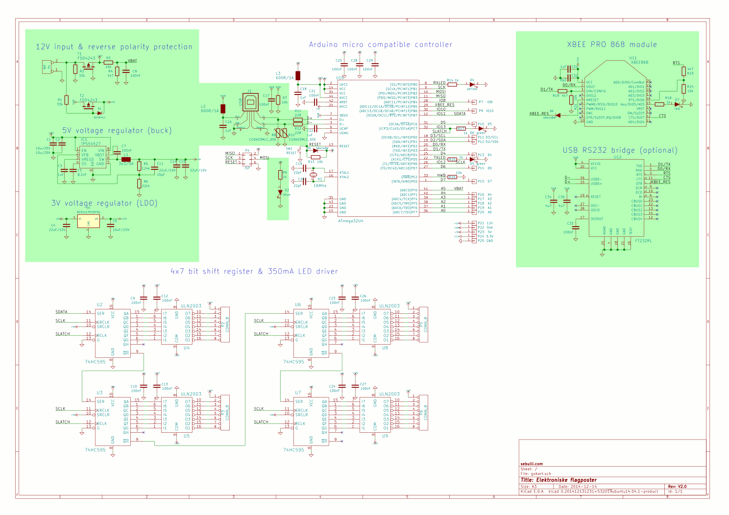
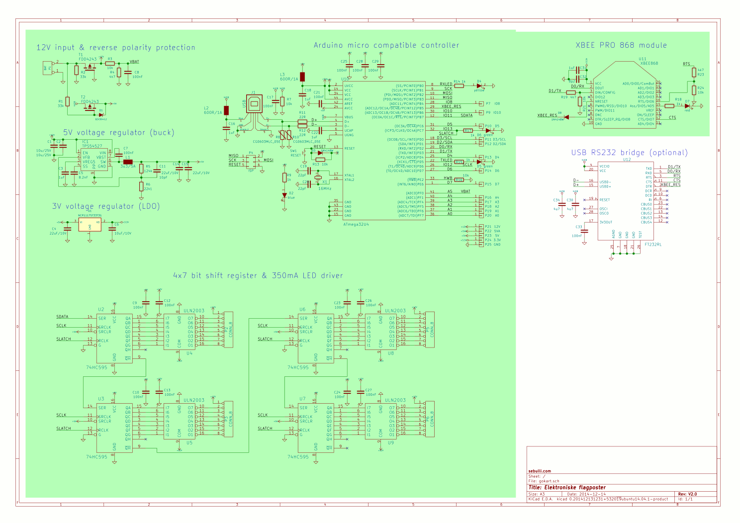
###Master module The master module is connected to a USB port of a PC or notebook. The master module can be supplied by USB or by an external 12V power supply. An external power supply is recommended on high power settings (If not, the blue LED is flickering).
###Panel module
If there is a new master module, update the radio.ino file with the master's XBee address and download it to all panel modules. The panels will only accept data from this master.
On startup, the software version, the battery voltage (120=12V) and the power setting (0..4) is displayed.
The XBee module is ready when all LEDs blink for a short time.
If then the testpoint P11 and P12 are connected together, the module displays the XBee address step by step and a display test is performed. Use this address to update the settings.txt
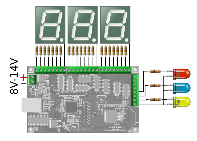
Use 7-segment displays with common anode. Voltage is 12V. Use external resistors in each line a..g
Connect LEDs to display the flag status. Connect the anode together.
The maximum current for 7-segment display or LED is 300mA per line.
##Your own Go-Kart track
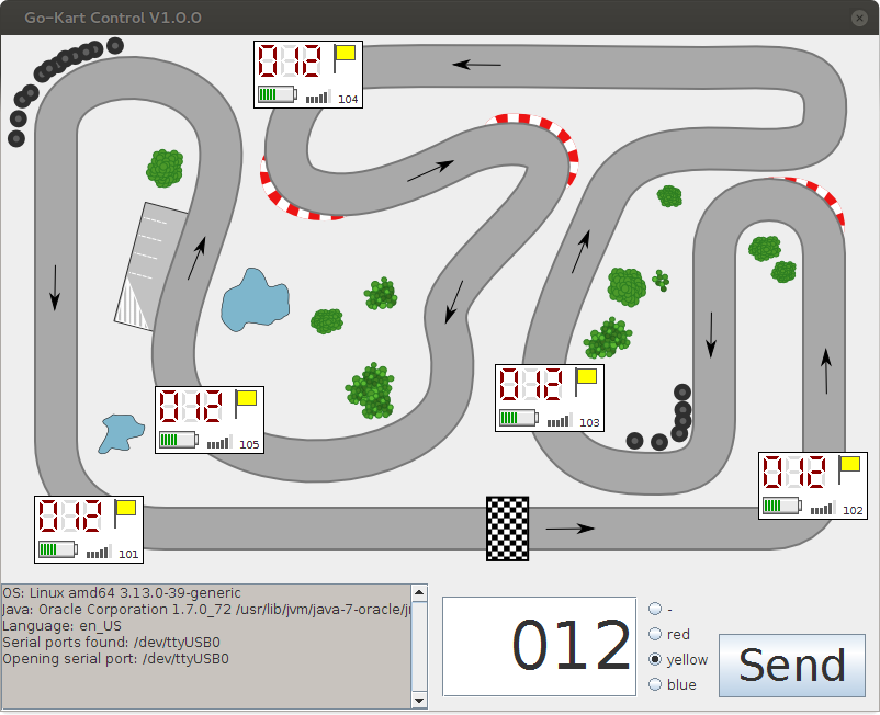
You can use the /pics/track.svg to generate you own background images for your go-kart tracks.
Edit this with Inkscape https://inkscape.org/de/ and export it as bitmap to your /pics folder. Filename is background.png.
Edit the settings.txt and change the x and y position of your panels.
