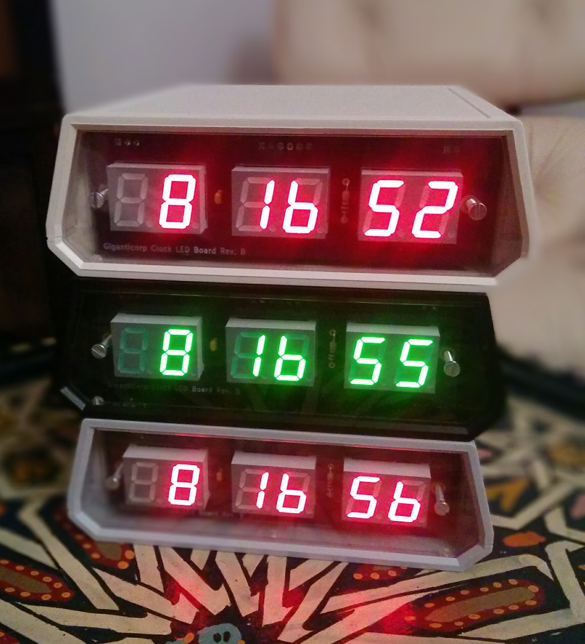
This project contains KiCad board schematics, PCB layouts, and firmware for my digital clock.
The clock features buttons to set the time, a hold button to aid in syncing the clock to another time source, and a switch to toggle the right-most display between showing seconds and the current temperature as reported by the real-time clock.
The clock is divided into two PCBs:
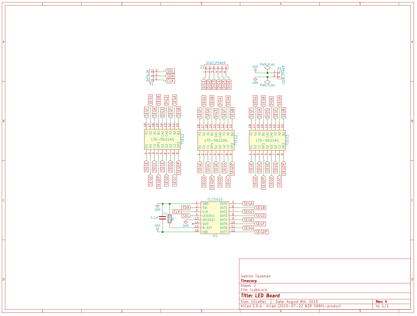
Schematic:
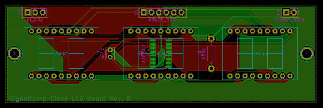
PCB Layout:
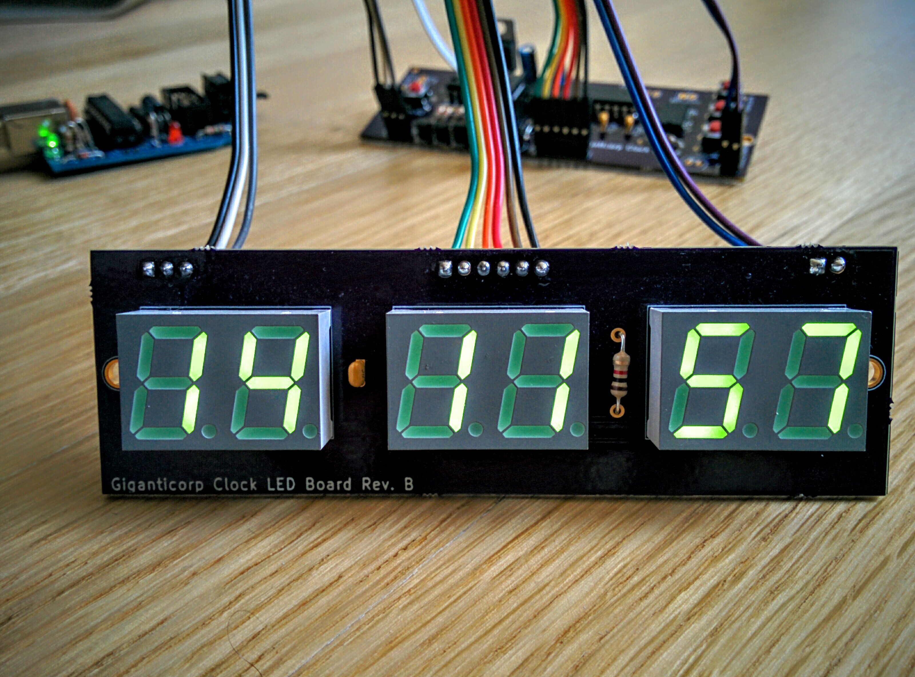
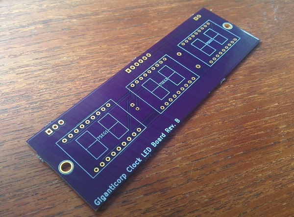
PCB fabricated by OSH Park:
This board contains:
- Three 2-digit 7-segment displays (Lite-On LTG-5612AG).
- A TLC5916 constant-current LED driver to drive the LEDs.
- A 0.1 uF decoupling capacitor for the TLC5916.
- A 1000 Ohm resistor to set the current allowed through the TLC5916.
- 6 power pins to drive the individual digits.
- 3 serial data pins to drive the TLC5916 (serial data, serial clock, latch).
- 2 pins for power and ground for the TLC5916.
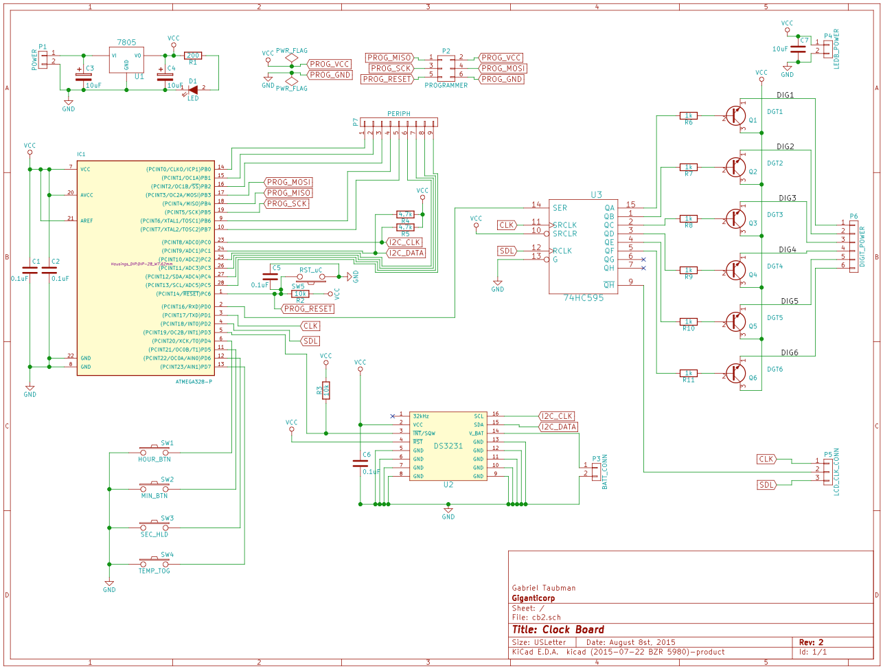
Schematic:
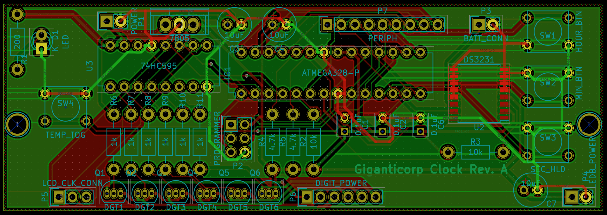
PCB Layout:
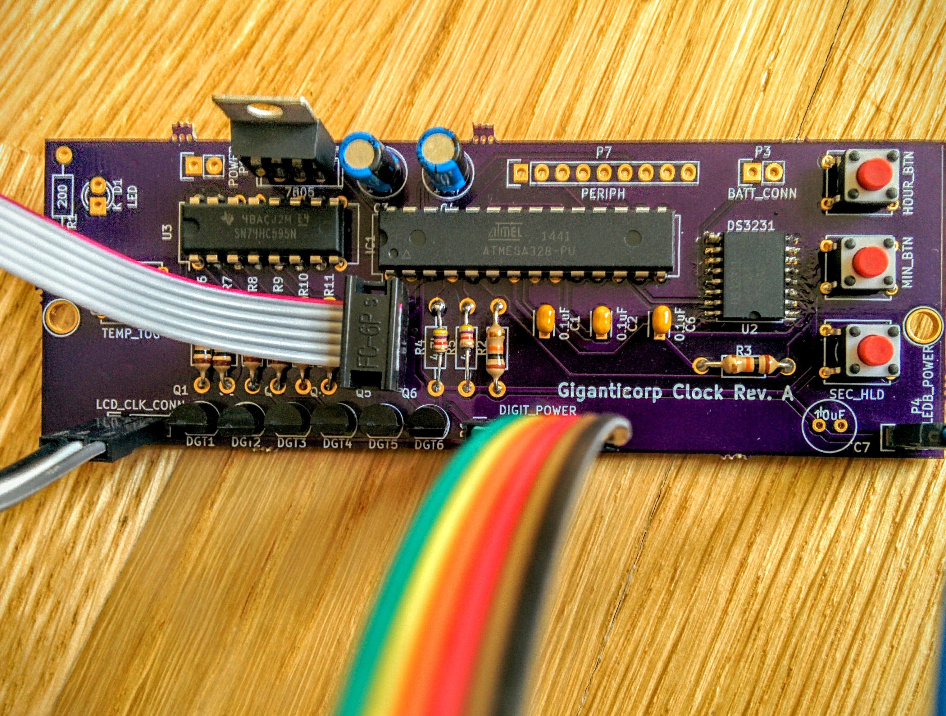
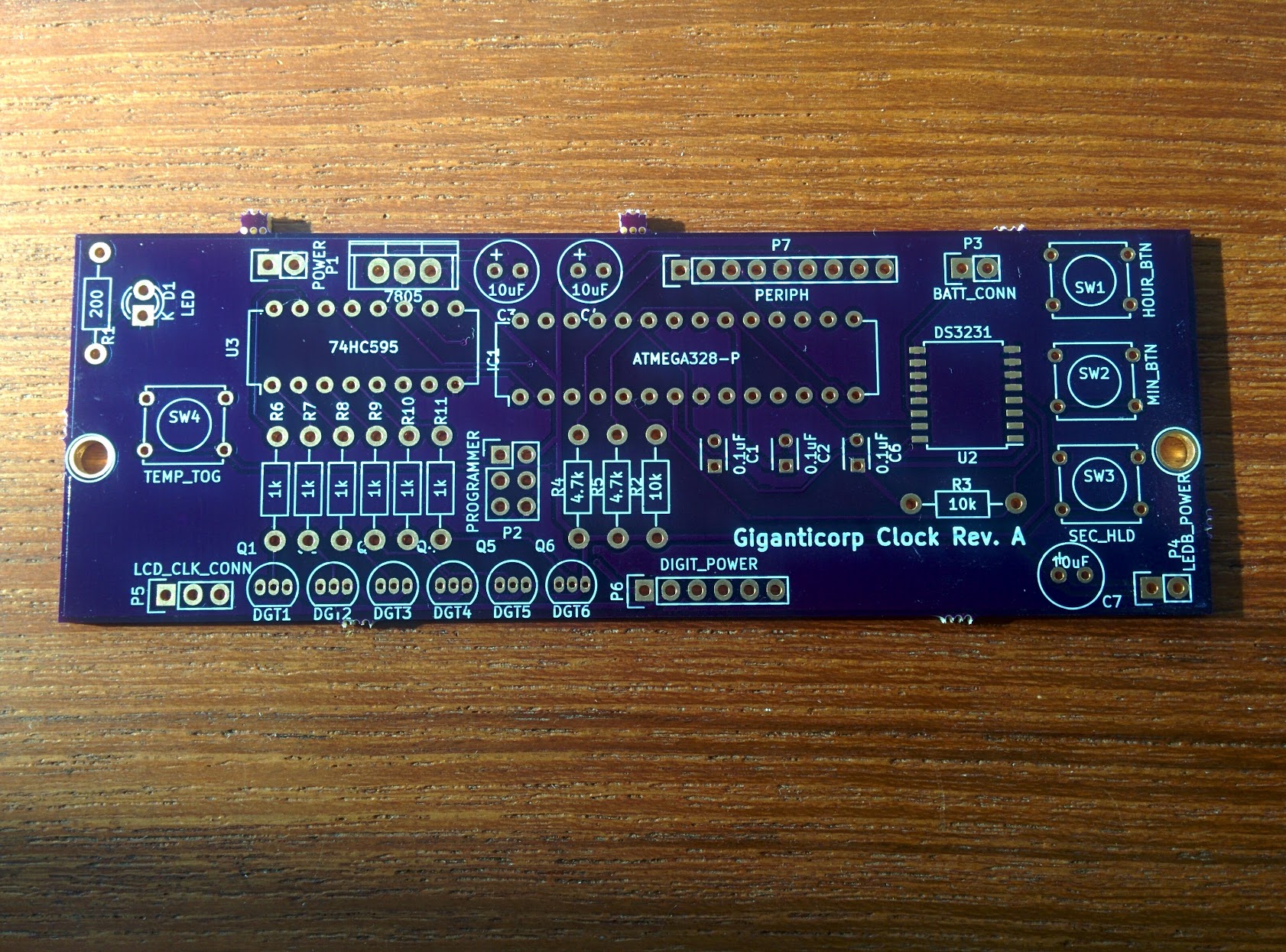
PCB fabricated by OSH Park:
The clock board is responsible for driving the entire clock logic, as well as interfacing with the real-time clock chip, and allowing user control over the clock functionality. It consists of:
- One Atmega 328pu running the show.
- One DS3231 real-time clock, communicating with the AVR over i2c.
- One 74HC595 shift register to control which digit is powered on.
- 6 transistors to power on digits.
- 6 1k, 2 4.7k, and 2 10k resistors.
- 4 push buttons for setting the time and temperature display modes.
- 3 decoupling capacitors.
- 2 10uF capacitors and a 7805 voltage regulator for supplying power.
- Pins to send power, data, and chip power to the LED board.
- An optional LED to indicate when the board is powered on.
