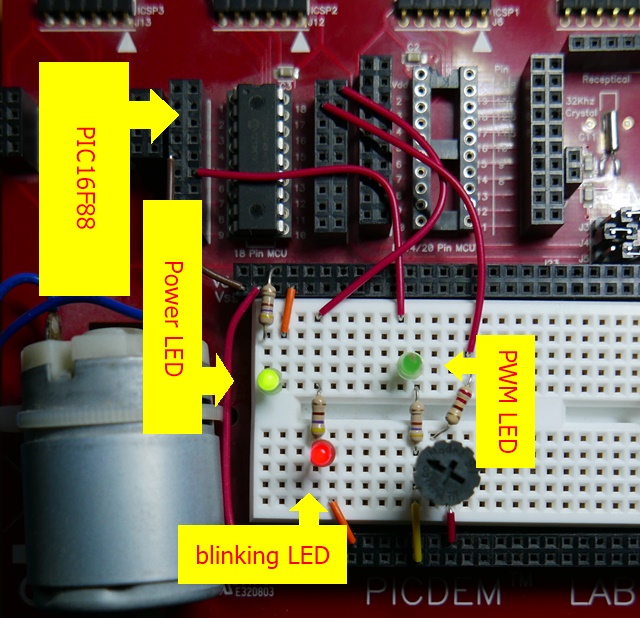
Demo project to read potentiometer value using ADC and output PWM to LED. I use it to learn how to use ADC and PWM on PIC16F88.
What it does (in a loop, around every 10ms):
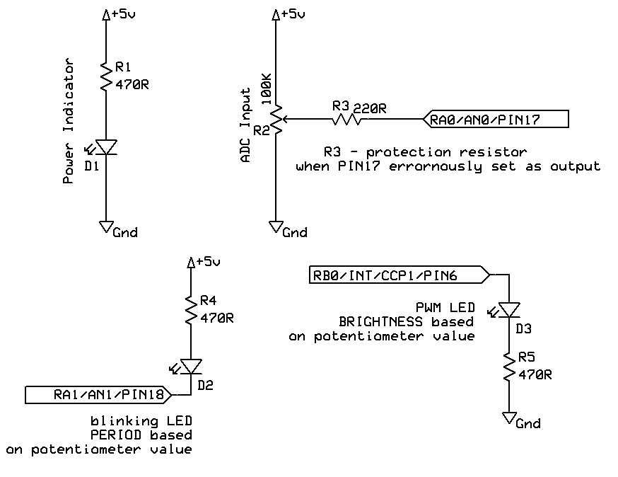
- Read potentiometer value using ADC, on
RA0/AN0/PIN17, ADC produces 10-bit value from 0 to 1023 (0x3ff) - set LED brightness on
RB0/INT/CCP1/PIN6using PWM - duty based on ADC value, PWM frequency is fixed at 1 kHz - Blinks LED on
RA1/AN1/PIN18, period based on ADC value, the shortest period is 50ms, longest is 1s
Used HW:
- PICDEM Lab Development Kit
- PIC16F88, note1 - included with latest series of DM163045
Schematic is below:
Important! These pins should be left not-connected for successful Programming and/or Debugging:
- PIN4 -
RA5/MCLR/VPP- for RESET and Programming voltage (RESET required for PIC to enter Programming mode, etc.) - PIN9 -
RB3/PGM/CCP1(x)- for Lov Voltage Programming (LVP) mode - PIN12 -
RB6/PGC/T1OSO/T1CKI- Programmer/debugger Clock - PIN13 -
RB7/PGD/T1OSI- Programmer/Debugger Data
If you connect load or capacity on any of above pins it may interfere with Programming and/or Debugging this chip.
Have to combine data from:
- PIC16F88, page 84, section
9.3 PWM Mode - DS40001369C, page 98, section
9.2.2 PWM Period - DS31014A, page 210 (14-8), section
14.5. PWM Mode
According to PIC16F88 datasheet, page 84, section 9.3.1 PWM Period there is:
So
And finally:
Or
Example for expected
So
Now we need to compute value Pulse Width 10-bit register CCPR. Let's say we want Pulse Width 25% = Ratio 0.25 (ratio is from 0 to 0.99999). The formula is:
Thus
For ratio 25% => 0.25 we get
Project under pic16f88_adc_pwm_c.X/. Requires latest software:
- MPLAB X IDE v6.05
- XC8 v2.40
- DFP 1.3.42
Listing is generated by default (at least under MPLAB X IDE v6.50):
pic16f88_adc_pwm_c.X/dist/default/production/pic16f88_adc_pwm_c.X.production.lst
- thanks to Project Properties -> XC8 Compiler -> Preprocessing and messages -> Generate ASM Listing file
Linker map file is generated in:
pic16f88_adc_pwm_c.X/dist/default/production/pic16f88_adc_pwm_c.X.production.map
- used my PIC16F88 project as template:
PICDEM Lab Development Board User Guide- DS40001369C
- used above guide for modified ADC circuit and ADC and PWM setup verification - but please note that this guide uses different PIC
Footnotes
-
PIC16F88 is one of few that has In-Circuit Debugger (ICD) which means that you can use them directly with suitable Debugger (PicKit3, ICD3, ICD4,...). Many other 8-bit PICs can't be debugged without special Adapter with emulation chip (called AC header). ↩

