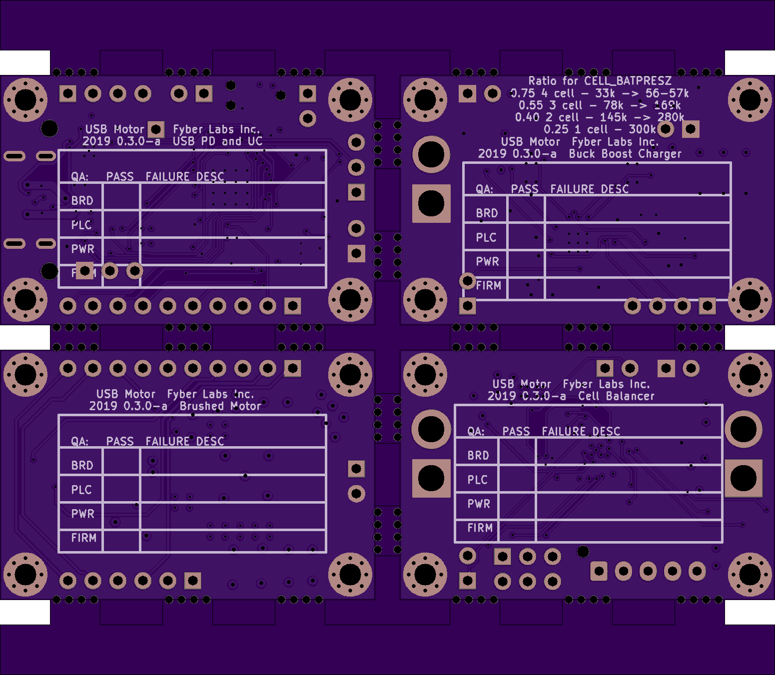
Variation on the Small Multicell USB Type C Charger, but with a specific purpose of making USB powered tools. There will be a brushless version eventually and a few other application variations. It supports a variety of rechargeable batteries and 1-4 cells depending on the solder bridge configuration.
For right now it has a single power/action button that can turn on/off, change speed, and reverse direction. A capacitive trigger or other more precise control can be added. There is also a reset button that can be removed after development.
These boards should 'mostly' stack in a 1x1.5" space with only a few wiring problems between them. This design has excessive FET control and filtering which can be reduced. Ideally, the design should fit on a single 1x1.5" board when developed for a specific application.
Assembly BOM Generated By InteractiveHtmlBom
GPL licensed firmware will be coming for the CCG3. I expect to use stock TI firmware for TI chips.
Notes:
- There will be bugs in the hardware and eventually they will hopefully be found and 'fixed.
- There are many solderbridges to disable FET controls and select cell counts as necessary.
- The CC 5V line on CCG3 should be routed or the 3v3 supply made 5V to fully enable a powerbank/OTG capabilities.
- Initial testing of some of the boards, so some logic may be incorrect.
- Developed with extra small designator silkscreen fonts which are likely to fail most PCB processes.
(They are not that important to my build process, and usually make a mess of the silkscreen either way.) - First panel attempted through oshpark
(Usually I remove edge lines on mousebites for other fabs, though this variation does make copper zones in KiCAD work better.)

