Micropython two axis analog joystick driver.
- Automatic x,y position polling with application callback or manual polling modes
- Reports position in either raw 0-65,534 u16 count or multi-tiered up/down/left/right states
- Independently reversible x and y axis to match wiring of joystick potentiometers
- Adjustable center 'dead zone'
There are two primary usage patterns: 1) internal driver polling of x,y position with application callback or 2) manual polling of x,y position from applicaiton.
In this mode of operation the driver polls the x,y position at a specified rate and updates the application via a callback.
from two_axis_analog_joystick import TwoAxisAnalogJoystick

# Joystick callback
def stick_cb(val):
    x = val[0]
    y = val[1]
    print("x count:", x)
    print("y count:", y)

# x potentiometer on pin 26, y potentiometer on pin 27, make measurement every 100ms and return raw x,y counts
stick = TwoAxisAnalogJoystick(26, 27, polling_ms=100, callback=stick_cb, callback_ret_raw=True)
stick.StartPolling()

# ...
# stick.StopPolling()In this mode of operation the application polls the driver for the current x,y position.
from two_axis_analog_joystick import TwoAxisAnalogJoystick
import time

# x potentiometer on pin 26, y potentiometer on pin 27
stick = TwoAxisAnalogJoystick(26, 27)

while True:
    val = stick.GetRawCount()
    x = val[0]
    y = val[1]
    print("x count:", x)
    print("y count:", y)
time.sleep(1)The driver can return the x,y position in raw 0-65,534 u16 counts or in mult-tiered up/down/left/right states.
If using internal driver polling with application callback, set the callback_ret_raw parameter to True to receive 'raw' values. The callback parameter will be a list containing two values. If using the manual polling mode, call GetRawCount() to return a list containing two values. The first item in the list will be the raw x value (0-65,534) and the second item in the list will be the raw y value (0-65,534).
With the joystick in resting centered position, the raw x,y values should each be approximately 1/2 the maximum count (i.e. [32,766, 32,766]). Moving the joystick to the left or right should increase or decrease the x count depending on how your potentiometers are wired. The same is true of the y count when moving the joystick up and down. The exact count values of center, fully up/down, fully left/right will vary depending on several factors including the resolution of your system's A/D, A/D reference voltage range and quality of the potentiometers and joystick construction.
Raw output may be obtained by calling GetRawCount() anytime or by specifying callback_ret_raw=True at initialization when using callbacks; the return value will be a list containing two elements, the u16 x count followed by the u16 y count.
An alternative to raw x,y counts are multi-tiered up/down/left/right states. In this mode each cardinal direction (up/down/left/right) is split into three equally* sized regions, MAX, MID, and MIN (see Image 1, 2).
*The Dead Zone lies at the very center and is subtracted from the total size of MIN.
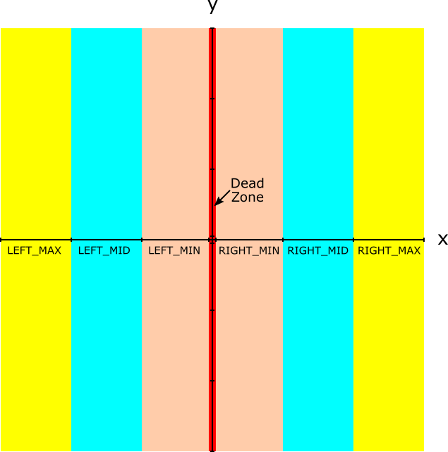 |
|---|
| Image 1: Joystick Regions On the X-Axis |
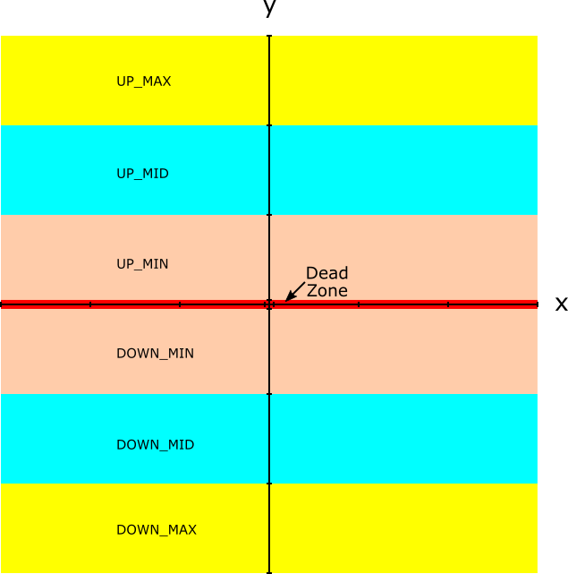 |
|---|
| Image 2: Joystick Regions On the Y-Axis |
The divisions between the regions are determined by the values of x1-x8 and y1-y8 (see Image 3).
 |
|---|
| Image 3: Region Values |
In its default state, the driver assigns the following values to x1-x8 and y1-y8:
| Marker | Raw Count Value |
|---|---|
| x1, y1 | 0x0000 (0d) |
| x2, y2 | 0x2AAA (10,922d) |
| x3, y3 | 0x5554 (21,844d) |
| x4, y4 | 0x7AFE (31,486d) |
| center | 0x7FFE (32,766d) |
| x5, y5 | 0x84FE (34,046d) |
| x6, y6 | 0xAAAA (43,690d) |
| x7, y7 | 0xD554 (54,612d) |
| x8, y8 | 0xFFFE (65,534d) |
| Table 1: Region Boundary Raw Count Mapping |
The x and y states are determined independently depending on which region the x,y coordinates lie between when measured. States corresponding to x will be MIN/MID/MAX variants of LEFT and RIGHT. States corresponding to y will be MIN/MID/MAX variants of UP and DOWN. When the x,y coordinates lie in the dead zone the CENTERED state is returned. The MIN/MID/MAX regions can be thought of as three ranges of joystick deflection. MIN represents a joystick delfected just beyond the dead zone of center. MID represents a joystick deflected approximately half way through its available travel. MAX represents a joystick deflected approximately full travel.
-
MAX Region
- If x1 <= x_measured < x2 then
SS_LEFT_MAXstick state is returned - If y1 <= y_measured < y2 then
SS_DOWN_MAXstick state is returned - If x7 <= x_measured <= x8 then
SS_RIGHT_MAXstick state is returned - If y7 <= y_measured <= y8 then
SS_UP_MAXstick state is returned
- If x1 <= x_measured < x2 then
-
MID Region
- If x2 <= x_measured < x3 then
SS_LEFT_MIDstick state is returned - If y2 <= y_measured < y3 then
SS_DOWN_MIDstick state is returned - If x6 <= x_measured < x7 then
SS_RIGHT_MIDstick state is returned - If y6 <= y_measured < y7 then
SS_UP_MIDstick state is returned
- If x2 <= x_measured < x3 then
-
MIN Region
- If x3 <= x_measured < x4 then
SS_LEFT_MINstick state is returned - If y3 <= y_measured < y4 then
SS_DOWN_MINstick state is returned - If x5 <= x_measured < x6 then
SS_RIGHT_MINstick state is returned - If y5 <= y_measured < y6 then
SS_UP_MINstick state is returned
- If x3 <= x_measured < x4 then
-
CENTERED Region (Dead Zone)
- If x4 <= x_measured < x5 then
SS_CENTEREDstick state is returned - If y4 <= y_measured < y5 then
SS_CENTEREDstick state is returned
- If x4 <= x_measured < x5 then
State output may be obtained by calling GetCurrentState() anytime or by specifying callback_ret_raw=False at initialization when using callbacks; the return value will be a list containing two elements, the const x state followed by the const y state. The values listed in Table 1 presume that the potentiometers of the joystick are wired with a specific polarity. The x and y axis values can be independently reversed to match other potentiometer wiring polarities as discussed in the next section.
The x,y states returned by GetCurrentState() or by specifying callback_ret_raw=False at initialization, when using callbacks, can be independently reversed to match joystick potentiometer wiring by supplying reverse_x=True or reverse_y=True at initialization or by calling ReverseX() or ReverseY() anytime. Reversal only applies to returned x,y states and does not effect raw x,y count values.
The dead zone is determined by taking the midpoint count 0x7FFE (32,766d) and adding/subtracting the driver default or user supplied dead zone value (see Table 1 x4/x5 and y4/y5 values). The driver default dead zone value is 0x0500 (1,280d). This value may be changed by supplying deadzone=new_value at initialization; the deadzone value must be selected such that the midpoint count 0x7FFE (32,766d) +/- the deadzone value does not exceed the values of x3/x6 and y3/y6.
The following is a simple example of using the internal driver polling (100ms between measurements) with a callback which returns the joystick x,y states. A persistent pixel is moved around a 128x128 px SD1327 based OLED display. The rate at which the pixel moves is determined by the x,y state; CENTERED results in no change, MIN deflections of the joystick result in 1 pixel 'jumps', MED deflections 3 pixel 'jumps' and MAX deflections 6 pixel 'jumps' each 100ms. This example was created and tested on a Raspberry PICO.
from machine import Pin
from machine import SPI
from sdd1327 import SSD1327_SPI
from two_axis_analog_joystick import TwoAxisAnalogJoystick
import two_axis_analog_joystick as TAAJ

# Setup display on SPI bus
spi = SPI(0)
dc = Pin(10)
res = Pin(11)
cs = Pin(12)
ssd1327 = SSD1327_SPI(128, 128, spi, dc, res, cs)

# Start pixel in middle of screen
screen_x = 64
screen_y = 64
ssd1327.pixel(screen_x, screen_y, 15)
ssd1327.show()

# Callback
def stick_cb(val):
    global screen_x, screen_y
    global ssd1327

    x = val[TAAJ.X_VALUE_LIST_INDEX]
    y = val[TAAJ.Y_VALUE_LIST_INDEX]

    # Adjust pixel x coordinate based on joystick deflection
    if (x == TAAJ.SS_LEFT_MIN):
        screen_x -= 1
    elif (x == TAAJ.SS_LEFT_MID):
        screen_x -= 3
    elif (x == TAAJ.SS_LEFT_MAX):
        screen_x -= 6
    elif (x == TAAJ.SS_RIGHT_MIN):
        screen_x += 1
    elif (x == TAAJ.SS_RIGHT_MID):
        screen_x += 3
    elif (x == TAAJ.SS_RIGHT_MAX):
        screen_x += 6

    # Bounds check
    if (screen_x < 0):
        screen_x = 0
    elif (screen_x > 127):
        screen_x = 127

    # Adjust pixel y coordinate based on joystick deflection
    # Note: for display, positive change is down, negative is up
    if (y == TAAJ.SS_DOWN_MIN):
        screen_y += 1
    elif (y == TAAJ.SS_DOWN_MID):
        screen_y += 3
    elif (y == TAAJ.SS_DOWN_MAX):
        screen_y += 6
    elif (y == TAAJ.SS_UP_MIN):
        screen_y -= 1
    elif (y == TAAJ.SS_UP_MID):
        screen_y -= 3
    elif (y == TAAJ.SS_UP_MAX):
        screen_y -= 6

    # Bounds check
    if (screen_y < 0):
        screen_y = 0
    elif (screen_y > 127):
        screen_y = 127

    # Display updated pixel
    ssd1327.pixel(screen_x, screen_y, 15)
    ssd1327.show()

stick = TwoAxisAnalogJoystick(26, 27, polling_ms=100, callback=stick_cb)
stick.StartPolling()