GPIO
The Raspberry Pi has a number of General Purpose I/O (GPIO) pins that make up a reasonable subset of the 40-pin header on the board (26-pin for earlier models).
Each of this pins is software programmable, with a number of different possible functions. The most basic two functions any pin can perform are to be configured as a digital input or a digital output.
Depending on the specific pin, a number of additional functions are available, handing off control of the pin to one of the other peripherals such as the PWM.
GPIO is covered in p89–104, particularly of note is the table of alternate functions on p102–103.
Probably the most difficult thing to understand is the multiple overlapping numbering schemes that are used for the Raspberry Pi's header pins and GPIOs, depending exactly which reference you're using.
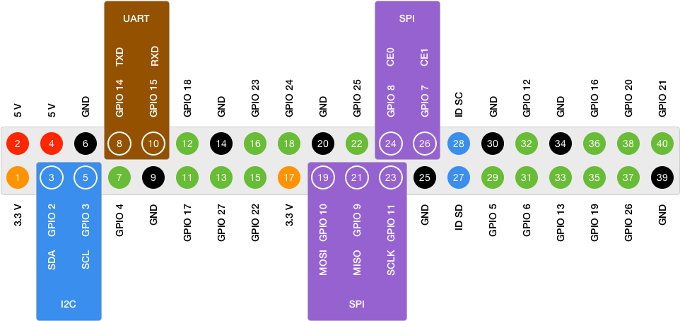
We can rationally use one of two numbering schemes:
- the Pin number on the header
- the GPIO number on the Broadcom chip
I suggest using the Broadcom numbering, since that's what the datasheet uses. Most breakouts, such as the Adafruit Pi T-Cobbler use the Broadcom numbering as well.
Watch out when using tools such as the gpio tool from Wiring Pi, that uses its own GPIO numbering scheme that doesn't match either the pins or the Broadcom datasheet! Pass the -g flag to force Broadcom numbering.
Just remember that when you work with GPIO 17, that isn't the same as Pin 17; GPIO 17 is on Pin 11, and Pin 17 is a 3.3V line.
The second thing to notice is that some of the pins on the header are already assigned to other peripherals by default, and not GPIO. These are shown on the pinout above, but specifically:
- GPIO 2 and 3 are mapped to I²C
- GPIO 14 and 15 are mapped to UART
- GPIO 7, 8, 9, 10, and 11 are mapped to SPI
We can change the behavior of these back to plain GPIO if we need to, but it's worth keeping in mind that if we want to use any of these peripherals, it's probably worth leaving them at their default mapping.
You'll also notice that there are gaps in the numbering and some GPIOs are not on the pinout:
- GPIO 0 and 1 are used for the ID SD and ID SC EEPROM pins, and cannot be re-used.
- GPIO 28–53 are mentioned in the specification but unavailable on the header.
Much of the internals of the Raspberry Pi, including things like the SD Card, use those later GPIOs. This is important because have to keep in mind that they exist.
Following the guides on Accessing IO Peripherals, Swift Pointers, and Integer Types we can map the GPIO registers into Swift. The offsets are given in the table on p90:
let peripheralBlockSize = 0x1000
let gpioRegistersOffset = 0x20000

guard let gpioRegisters = mmap(nil, peripheralBlockSize, PROT_READ | PROT_WRITE, MAP_SHARED, memFd, off_t(peripheralAddressBase + gpioRegistersOffset)),
      gpioRegisters != MAP_FAILED else { fatalError("Couldn't mmap GPIO registers") }
Looking through this table, we can see that the registers mostly come in clusters of two, with the exception of the GPIO Function Select register, which is the one that we need right now, that is a cluster of five separate registers starting at the base address.
The tables on p91–94 give a verbose explanation of the pins of these registers, but it's really quite simple. The possible functions for each GPIO are represented by a three-bit value, from the following table:
| Bits | Function |
|---|---|
| 000 | Input |
| 001 | Output |
| 100 | Alternate Function 0 |
| 101 | Alternate Function 1 |
| 110 | Alternate Function 2 |
| 111 | Alternate Function 3 |
| 011 | Alternate Function 4 |
| 010 | Alternate Function 5 |
Since each GPIO needs three bits, only the functions of ten GPIOs can be selected with one 32-bit word; and as there are 54 GPIOs—numbered 0 to 53—five words are required. Thus there are five registers; register 0 sets the functions of GPIOs 0–9, register 1 for 10–19, and so on until register 5 for 50–53.
Within a register the bits are shifted into the fields for each GPIO. Within register 0, bits 0–2 are for GPIO 0, 3–5 for GPIO 1, etc.
Thus in order to select the function of a GPIO, we need to do four things:
- Select the correct register.
- Select the correct bit offset within the register.
- Mask out any existing value for the GPIO.
- Set the new value.
Masking is important because if we tried to simply set the GPIO to an output (001) by ORing with the current value, and the GPIO was previously alternate function 2 (110), it would end up as alternate function 3 (110) instead.
Selecting the correct register and bit shift is easy enough, since there are ten GPIOs per register, we can divide by ten; and then since there are three bits per GPIO, we multiply the remainder by 3:
let gpio = 17
let newFunction = 0b001

let register = gpio / 10
let bitShift = (gpio % 10) * 3
Swift doesn't have a direct equivalent of C's fixed-length arrays, so when it comes to mapping the register cluster, we have two options. The first is to use a structure of five variables, and implement a subscript or similar to select the right one; the second is to rely on the existing subscript behavior of UnsafeMutablePointer<T>, which is what I've done here:
let functionSelectOffset = 0x00

let functionSelect = gpioRegisters.advanced(by: functionSelectOffset).bindMemory(to: Int.self, capacity: 5)

let registerValue = functionSelect[register] & ~(0b111 << bitShift)
functionSelect[register] = registerValue | (newFunction << bitShift)
We use a temporary variable here, rather than &= and |= to avoid toggling the GPIO function briefly to Input.
Now the register is ready for output.
Before we delve into the different functions, it's worth revisiting the register table again. The GPIO Function Select cluster had five registers, but the rest of the register clusters have just two registers each.
Specifically:
- GPIO Pin Output Set
- GPIO Pin Output Clear
- GPIO Pin Level
- GPIO Pin Event Detect Status
- GPIO Pin Rising Edge Detect Enable
- GPIO Pin Falling Edge Detect Enable
- GPIO Pin High Detect Enable
- GPIO Pin Low Detect Enable
- GPIO Pin Async. Rising Edge Detect
- GPIO Pin Async. Falling Edge Detect
- GPIO Pin Pull-up/down Enable Clock
Only two registers are needed in these clusters because only one bit is used for each GPIO. The first register in the cluster has the bits for GPIOs 0–31, while the second has 32–53.
We can use the same pointer binding trick as above, just with a capacity of two. Selecting the appropriate register and bit is thus:
let register = gpio / 32
let bit = 1 << (gpio % 32)
There's one more detail of these registers that's important: when performing a write on a register, the hardware ignores all zero bits.
That means if we want to toggle a bit to true, we can simply write the value of bit to the register. The fact the value has zeros for the rest of the GPIOs is ignored by the hardware.
If we set multiple bits in the value to one, the resulting write sets the values of all of the GPIOs for those bits at once, but again any other GPIO for which the bit is still zero is ignored.
As a result, these registers operate as either read/clear, or in set/clear pairs. We'll cover these in the function examples.
For a GPIO set to the Output function, there are two register clusters that operate as a set/clear pair:
- GPIO Pin Output Set
- GPIO Pin Output Clear
In order to control output, we need to map both of them:
let pinOutputSetOffset = 0x1c
let pinOutputClearOffset = 0x28

let pinOutputSet = gpioRegisters.advanced(by: pinOutputSetOffset).bindMemory(to: Int.self, capacity: 2)
let pinOutputClear = gpioRegisters.advanced(by: pinOutputClearOffset).bindMemory(to: Int.self, capacity: 2)
To set a GPIO output to a +3.3V high, you write one bits to the GPIO Pin Output Set register, corresponding with the GPIO:
pinOutputSet[register] = bitWe can set multiple GPIOs high in this one write by setting more bits in the value to one.
But if zeros are ignored, how do we set the GPIO output to a 0V low? The answer is the second register cluster, the GPIO Pin Output Clear register. When a one is written to this, it clears the value:
pinOutputClear[register] = bitAgain we can set multiple GPIOs low in this one write by setting more bits of the value to one.
These two register clusters thus behave as a set/clear pair. Whether we want to set a GPIO to high or low, we always write a one since zeros are ignored. We change the register, not the bit value.
Using a GPIO directly for input is even easier since we only have to read the values from the GPIO Pin Level registers. The appropriate bit for a GPIO will be true if the GPIO is high, and false if it is low.
(There's an error in the datasheet that claims it's zero for both, don't believe it.)
let pinLevelOffset = 0x28

let pinLevel = gpioRegisters.advanced(by: pinLevelOffset).bindMemory(to: Int.self, capacity: 2)

let high = (pinLevel[register] & bit) != 0
This will give the actual level for the GPIO regardless of what mode it is in, so it can also be used to view the current level of a GPIO that is in output more.
To monitor the value of an input GPIO, you can simply poll the value of the appropriate register regularly. More advanced input scenarios are available through the other registers, however.
I haven't had a need to play with these yet, documentation to write when I do...