Using GPIO to generate DCC signal
The Raspberry PI offers a number of hardware peripherals that may be suitable for generating the basis of a DCC signal. These are documented in the Peripherals datasheet for the original model of the Pi, with an errata maintained by the eLinux group.
As with such things, there's a number of missing details that are crowd-sourced from various projects, a good source of constants is the gertboard demo code.
The Raspberry Pi has a number of General Purpose I/O pins (GPIO) that make up a reasonable subset of the 40-pin header on the board. These are software programmable, and one of the most basic things we can do is to set them to output 3V or 0V as desired.
Obviously this isn't sufficient voltage for DCC, and likewise the maximum current of 16mA per pin, 51mA combined, wouldn't drive a single locomotive; however this can be addressed by a booster circuit later. A well-timed logic signal is sufficient.
We can try a simple bit blaster approach and see.
The first thing that we need to do is to map the address space for the GPIO registers into our process's address space, which we can do through /dev/mem.
For the Pi 3B that I am using, the address base of all of the peripherals is 0x3f000000 (older models use 0x20000000), and the GPIO registers can found as a 4K page at the 0x200000 offset.
let peripheralAddressBase = 0x3f000000
let peripheralBlockSize = 0x1000

let gpioRegistersAddress = peripheralAddressBase + 0x200000

let memFd = open("/dev/mem", O_RDWR | O_SYNC)
guard memFd > 0 else { fatalError("Couldn't open /dev/mem") }
defer { close(memFd) }

guard let gpioRegisters = mmap(nil, peripheralBlockSize, PROT_READ | PROT_WRITE, MAP_SHARED, memFd, off_t(gpioRegistersAddress)) else { fatalError("Couldn't mmap GPIO registers") }
This gets us a pointer that we can use to manipulate the GPIO registers. We also need to pick a GPIO pin to use. There are multiple numbering schemes for each pin, for the purposes of testing, I'm picking the pin named GPIO0, which is numbered GPIO pin 17 for the Broadcom chip, but pin 11 on the header.
Since register numbering uses the Broadcom GPIO pin numbering, we go with that.
let gpioPin = 17Each pin can be set to a basic input, or output function, as well as a number of alternative functions. We want output, which we achieve by writing 001 for the appropriate bits of the pin's Function Select register.
The math of this looks a bit weird, but it's pretty simple in practice. There are six 32-bit Function Select registers, each addressing 10 pins with 3-bits each to select the mode.
In the first line we obtain a pointer to the specific Function Select register which handles this pin (and others), we then mask out any existing setting for that pin (reverting it to 000 briefly), before setting it to output.
let gpioFunctionSelect = gpioRegisters.assumingMemoryBound(to: UInt32.self).advanced(by: gpioPin / 10)

gpioFunctionSelect.pointee &= ~(0b111 << UInt32((gpioPin % 10) * 3))
gpioFunctionSelect.pointee |= 0b001 << UInt32((gpioPin % 10) * 3)
Setting a pin is simpler; the Broadcom chip uses two reigsters, both of which ignore any 0s written to them. Writing 1 to any bit in the Pin Output Set register sets that pin to high (3V), while writing 1 to the same bit in the Pin Output Clear register sets that pin to low (0V).
We can toggle multiple pins at the same time by setting more than one bit to 1, but we can also toggle pins without affecting others by leaving them at 0.
Since the documentation gives a fixed offset of 0x1c and 0x28, we first advance the raw pointer to this location, before binding it to 32-bit so we can advance it again if necessary.
let gpioPinOutputSet = gpioRegisters.advanced(by: 0x1c).assumingMemoryBound(to: UInt32.self).advanced(by: gpioPin / 32)
let gpioPinOutputClear = gpioRegisters.advanced(by: 0x28).assumingMemoryBound(to: UInt32.self).advanced(by: gpioPin / 32)

let gpioPinBit = 1 << UInt32(gpioPin % 32)
Now to generate a signal, we can simply loop, writing values to these pointers and sleeping.
while true {
    gpioPinOutputSet.pointee = gpioPinBit
    usleep(58)
    gpioPinOutputClear.pointee = gpioPinBit
    usleep(58)

    gpioPinOutputSet.pointee = gpioPinBit
    usleep(58)
    gpioPinOutputClear.pointee = gpioPinBit
    usleep(58)

    gpioPinOutputSet.pointee = gpioPinBit
    usleep(100)
    gpioPinOutputClear.pointee = gpioPinBit
    usleep(100)
}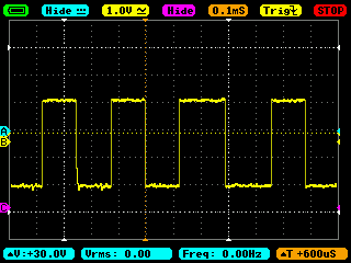
This gives us, at first glance, a reasonable output; however these are a number of drawbacks to this approach which make it non-desirable.
The most obvious one is that Linux isn't a real-time operating system, and makes no guarantees about the exact timing of operations. The DCC specification is very sensitive to timing, and it's not enough to rely on the software being scheduled often enough to match it.
Since one thread would have to be continually driving the hardware, it then also becomes problematic to even schedule such things as reciving updates from the rest of the code, let alone the rest of the code requiring scheduling time in of its own right.
A more hardware-oriented solution is preferred.