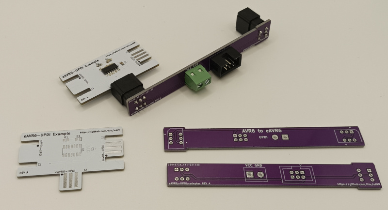
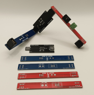
eAVR (edge AVR) replaces the standard 6P (2x03) pinheader or 6P (2x03) IDC socket for AVR device programming and debugging (aWire, PDI, SPI, TPI, UPDI) with an edge connector, reducing your BOM costs and soldering efforts.
Besides the card edge footprints this project includes adapter boards to interface the standard AVR 6P connector to the required card egde connectors.
This repository features footprints, adapters and example boards.
- eAVR.pretty: Footprints for KiCad
- eAVR6-adapter-hrz: A card edge to 6pin horizontal adapter
- eAVR6-adapter-vrt: A card edge to 6pin vertical adapter
- eAVR6-example: An example board using TPI
- eAVR6-UPDI-adapter: A card edge to 6pin adapter for UDPI only
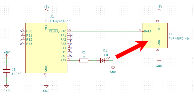
- eAVR6-UPDI-example: An example board using UPDI
This is NOT an official standard or related to anything official by Microchip Technology Incorporated. This is a hobby standardization attempt to improve the quality of life for AVR developers.
Be aware that with "cheap" PCB fabrication, your edge contacts will wear out quickly. It is not recommended to use this technique in scenarios where many insertions are required. If you need a long term reliable solution either specify ENIG/Gold Fingers options with your board house or go back to using the standard 6P pinheader / IDC socket. There is unfortunately no free cake.
In order to gain the benefits of eAVR you need to incorporate the edge connector footprints into your designs and build an adapter interfacing the standard 6P AVR connector with an edge card connector once.
This project offers two different options moving forward:
The generic option is a 1:1 translation of the standard 6P connector towards the card edge offering the expected full functionality (aWire, PDI, SPI, TPI, UPDI) of an AVR connector. The footprints and adapters include a polarity marking to ensure correct orientation on insertion.
The other option is a specialised solution for devices using UPDI. As UPDI requires three connections only, this can be mirrored on a 2x03 connector. This option results in a polarity/orientation free connector and offers the possibility to place the edge connector only on one side of your board.
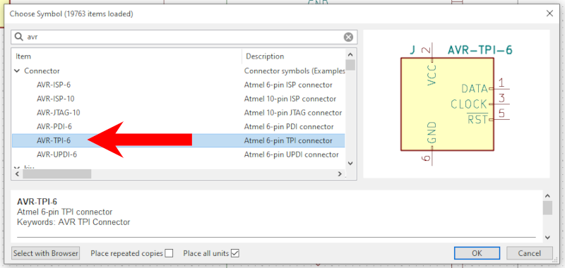
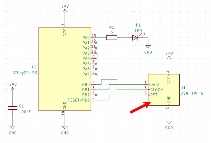
In your schematic use one of the "AVR-ISP-6, AVR-PDI-6, AVR-TPI-6, AVR-UPDI-6" symbols from the "Connector" package as you would normally do.
Assign the "eAVR6" footprint from the "eAVR" package delivered by this project.
Place the footprint on your board, route your signals and connect the edge cuts depending on your layout. See below for details.
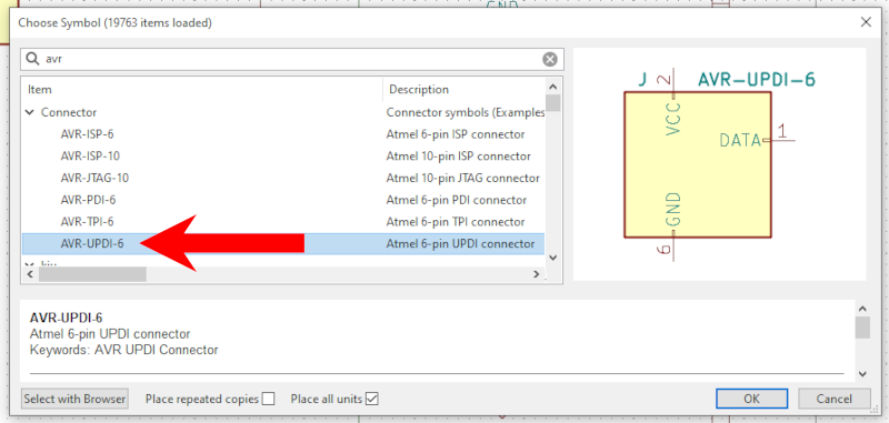
In your schematic use the "AVR-UPDI-6" symbol from the "Connector" package as you would normally do.
Assign one of the "eAVR6-UPDI-*" footprints from the "eAVR" package delivered by this project. There are three variants available providing contacts on either "-F"ront, "-B"ack or "-FB" both sides.
Place the footprint on your board, route your signals and connect the edge cuts depending on your layout. See below for details.
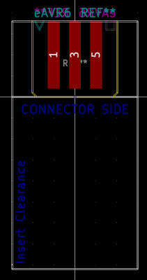
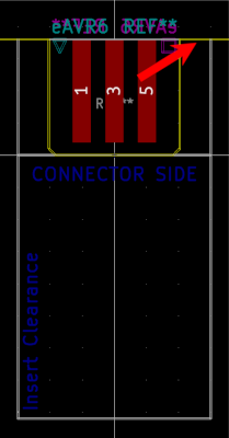
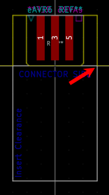
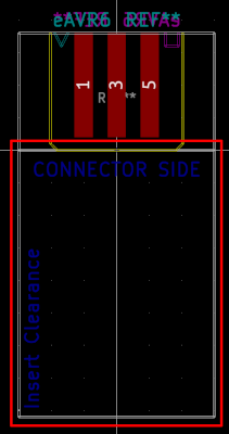
The footprint itself offers guidance on where Edge.Cuts need to be connected to including the required clearances.
You can either let the connector "stick out" of your board...
... or let the connector be "recessed" into your board. In either case, use the User.Drawings as guidance for your Edge.Cuts placement.
If you want to be able to plugin the connector once your board is placed into an enclosure, make sure the marked clearance area is kept free of obstacles.
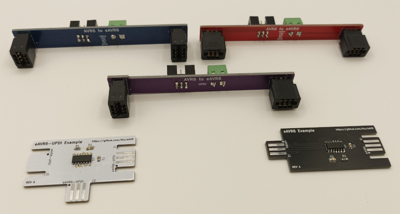
This is an example of both variants being incorporated into a simple demo board.
To connect your AVR programmer/debugger with the edge connector you need to build an adapter once. This project contains three different edge adapters all interfacing the standard 6P 100mil AVR connector with additional terminal screws for optional power injection.
The eAVR6-UPDI-adapter is for UPDI only boards ...
... while eAVR6-adapter-hrz and eAVR6-adapter-vrt are for generic boards offering a layout for vertical and horizontal insertion.
The required 6P (2x03) card edge connector with 2.54mm (100mil) pitch needed to interface with eAVR can easily be obtained from e.g.:
