Master clock for Lepaute 30 seconds alternating pulse slave clock and possibly other models.
Slave clocks are old school clocks mostly used in train stations, hospitals, factories, etc... places that needed to have accurate timekeeping and synchronized clocks in a lot of places. A master clock was responsible for keeping time and controlling all the slave clocks. There were a number of clock manufacturers, and there were a lot of way of synching the slave clocks to the master clock.
If you find a beautiful industrial slave clock, there are several options :
- Find the master clock to go with it, but you'll need space, money and time to take care of it
- Remove the old mechanical movement and replace it with a quartz one (shame on you)
- Buy one of these, but what's the fun in that ?
- Make a teeny-tiny master clock.
So here comes this project.
I got hold of two slave clocks that were salvaged from an hospital that was being destroyed in France. One of them is a Lepaute clock.
Those clocks use an alternating pulse every 30 seconds to make the minute hand advance half a minute. The pulse is ~200ms and a 1.5V battery is enough to make it go.
I wanted to make a board that could run for more than a year on a single AA battery, be highly accurate and that would be as small as possible (in this case, just enough space to fit the battery and a screw terminal to plug the clock mechanism).
That was a fail, but mostly due to firmware mistakes. Old one had flaws and kept the clock running approximately 3 1/2 weeks before draining the battery. This new version of the firmware should improve the run time dramatically. New version with new battery installed on February 27 2018 at 8:30PM, let's see how long it'll run...
When all the chips are sleeping, my multimeter shows nothing, and the wake-up time is so short that I can't measure it precisely. I've gotten a uCurrent Gold, so I can measure some current consumptions, but I'm running into problems getting it to work with my oscilloscope. I'll update with curves and graphes when possible.
Full BOM can be found on mouser
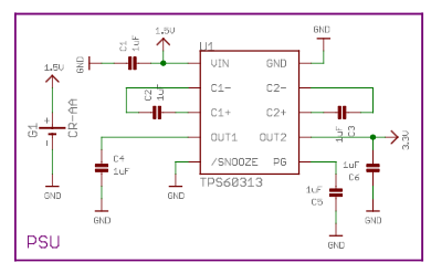
- TPS60313 : Charge Pump
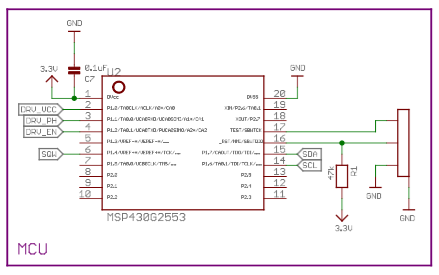
- MSP430G2553 : MCU
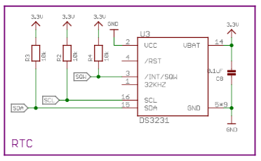
- DS3231SN : I2C RTC
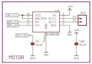
- DRV8838 : Brushed DC Motor Driver
Power is provided by a single AA battery.
A TPS60313 converts this voltage to 3V in order to power the MCU and RTC. Input voltage can go as low as 0.9V in order to get 3V output. Quiescent current at no-load is 35uA.
MCU is an MSP430G2553 spending most of its time in LPM4 (consumption should be about 0.15uA). uCurrent shows around 0.105uA.
RTC is a DS3231SN, powered only via VBAT to reduce the current consumption of the device. According to the datasheet, Ibatt goes up to 70uA when active, while Ivcc goes up to 200uA. Ibatt when only timekeeping is 0.84uA typical. Measuring with a uCurrent gold shows this number to be accurate. A DS3231M could be used, but the SN is a tad bit more accurate (+/-2PPM against +/-5PPM for the M).
To drive the mechanism, an alternating pulse is necessary. This could be done with a discrete H-bridge, but I opted for a DRV8838, directly powered from an MCU pin. This way, the DRV isn't even sleeping, but only switched on when needed, once every 30 seconds. Vmotor comes directly from the AA battery.
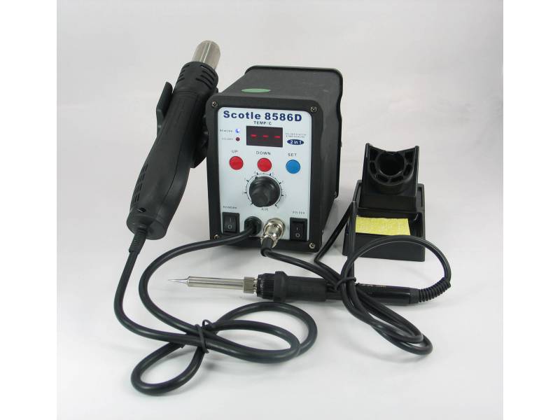
This board being an exercise in miniaturisation, all the resistors and caps are 0402... I advise you not to try to solder this board without a good-ish soldering iron and an hot air gun. I'm using one of the cheap chinese all-in-one stations, but without hot air, some components are next to impossible, especially the DRV8838.
Firmware was developed using TI's Cloud IDE since I'm using a Mac and it was the simplest solution.
New version of the firmware configures the RTC to ring 2 alarms : one every time the time goes past HH:MM:00s, the other every time the time goes past HH:MM:30s. The RTC will pull low the interrupt pin 8ms every 30 seconds. Power consumption when the pin is high is microscopic, but it goes up when pulled low. The old firmware was generating a 1Hz square wave with a 50% duty cycle, so the higher current consumption was happening 50% of the time. Now, it should happen only 16ms / minute or 0.00027% of the time...
Old version for information purpose :
On boot, the MSP430 runs at 1MHZ and sets some configuration on the RTC :
 * Enable Oscillator
 * Battery-Backed Square-Wave Enable allows the interrupt to be sent when powered by VBAT
 * Rate Select set to 1Hz
 * Interrupt Control set to Square-Wave
 * Disable Alarms
P1.4 of the MSP430 is set as an interrupt pin, and then it is put to sleep with external interrupts enabled (LPM4 + GIE).
Every 30 seconds, the RTC pulls P1.4 low, which wakes up the MSP430. We start by clearing the alarm flags of the RTC. A var to keep the inversion of the phase pin is used to check if we should pull P1.1 high or low and inverted each time. We can then proceed to send the enable signal to the DRV8838 so that we advance the needle one step.
MSP430 current consumption while in LPM4 is around 105nA, and 370uA when awaken. The old firmware was waking it up every second for a couple cycles, and then for a full 200ms while sending the pulse every second. Now, we only wake up the MSP430 every 30 seconds for the full 200ms. The old firmware was also toggling the state of P1.1 every 30 seconds, so it was staying high for a full 30 seconds before being toggled low. Now, it's only pulled high if necessary.
Old version for information purpose :
Each second, the RTC sends a pulse on P1.4, which wakes up the MSP430. A counter is incremented and when this seconds counter == 30, power is applied to the DRV8838 by putting P1.0 high (DRV_VCC), pulse direction is reversed by toggling P1.1 (DRV_PH) and a 200ms pulse is sent via P1.2 (DRV_EN). Counter is reset and the MSP430 goes back to sleep.

