GunnsFluidConductor

This link is the simplest fluid conductor and the base class for most other conductors such as pipes, valves, etc. The link flows w in proportion to the node delta-pressure dp as:
where G is the link's effective conductivity, rho_avg is the average of the node fluid densities, and x is a configurable exponent on the pressure effect (defaults to 1/2). With the default exponent of 1/2, this is the momentum equation for steady one-dimensional flow, with a simple correction for compressibility. Conductivity G is tuned to give the desired flow at a given delta-pressure. This equation ignores body forces, viscous shear forces and momentum exchange with the outside - the viscous effect is usually included in the tuning of G.
The link models the cooling of a gas as it expands across the pressure drop. This is called isentropic expansion, and the amount of this effect can also be tuned. Apart from this optional temperature change due to expansion, this link does not model any thermal effects and no other changes to temperature are done.
The link does not modify the mixture of the fluid passing through it.
This picture shows the various ways fluid conductors can be connected to nodes, and one way they can't. Putting both ports on Ground is a good way to store spare links.
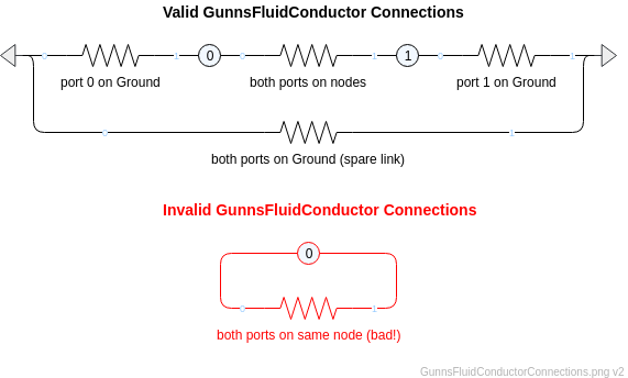
Port Connection Rules (These are limitations on the port connection to nodes that the link enforces in run-time):
- Ports 0 and 1 cannot connect to the same non-Ground node.
Other Rules (These are extra rules you should always try to follow):
- Do not mix fluid phases across the link. That is, both nodes should contain the same phase (gas or liquid), and not different phases.
- Use this link in lieu of more complicated conductors such as pipes, valves, etc when you simply need to flow from one node to another and don't need any additional thermal, mixing or variable conductivity effects.
- In general, try to combine conductors in series into a single conductor whenever possible.
This reduces the network node count, which can save a lot of CPU. For instance, a fan (which
derives from this conductor class) in series with a filter and a long duct (which would normally
be modeled with 2 more conductor links) can be combined into one fan link - the fan's conductivity can be reduced to
model the flow resistance of the filter + duct, etc. A number X of conductors in series all
with conductivity G_x is approximately equivalent to a number Y of conductors in series all with
conductivity G_y, by the following relationship between G_x and G_y:
(G_x / G_y) = sqrt( X / Y )
This relationship can help you merge series conductors and keep the flow performance of the overall chain the same.
Configuration Data Parameters:
- maxConductivity (default = 0.0 m2, must be >= 0 and in general you should limit non-zero values to be between 1.0E-15 and 1.0E+15): This is the maximum conductivity the link takes when it is not blocked. This parameter usually has to be tuned or tweaked to give the desired flow rate at a given delta-pressure, because the flow equation is only an approximation and is not accurate enough to predict correct flow rate of a real flow path in all cases. A rule of thumb is to start with the real cross-sectional area of the simulated flow path, and the final tuned conductivity will generally be within one order of magnitude of the initial area in most cases. There is also a tuning helper spreadsheet in your GUNNS repo at (works best with MS Excel): gunns/aspects/fluid/tuning/Gunns_Pipe_Tuning_Helper.xlsx. This spreadsheet predicts the best conductivity for a simple pipe geometry and desired flow rate. The blockage malfunction (described below) further reduces the effective conductivity used in the flow equation from this maximum conductivity.
-
expansionScaleFactor (default = 0.0, must be (0-1)): This scales the temperature drop of gas flow thru the
link in response to the pressure drop. A value of 1.0 gives the full theoretical amount of temperature
change from isentropic flow theory:
T1 / T0 = (P1 / P0) ^ ((gamma-1) / gamma),
where gamma is the fluid's adiabatic index (ratio of specific heats). An expansionScaleFactor value of 0.0 turns this effect off. This effect only applies to gas phase, and for liquids the term is ignored. - mPressureExponent (Input file only) (default = 0.5, must be (0.5-1)): This is the exponent x in the flow equation (above). It defaults to 0.5, which is typical of most flows. A value of 1 is useful for modeling the linear flow vs. pressure trend of laminar flow. Note that this term is not in the GunnsDraw shape data, so if a value other than the default 0.5 is needed, you must set it via the input file. For example, for a conductor link named "myConductor" in network "myNetwork", it would appear like this in the input file: myNetwork.netConfig.myConductor.mPressureExponent = 1.0.
Input Data Parameters:
- malfBlockageFlag (default = false): Initial state of the blockage malfunction activation flag. This malfunction reduces the effective conductivity from the maxConductivity value.
- malfBlockageValue (default = 0.0, must be (0-1)): Initial state of the blockage malfunction activation value. A value of 0.0 is the same as no blockage at all, and 1.0 completely blocks all flow and isolates the port nodes from each other (although parallel flow paths still apply).
-
Chasing pressures when tuning: When tuning the conductivity, you are usually looking for the value
that gives the desired flow rate at a given delta-pressure. However, when you change the conductivity, not only
does that increase or decrease the flow rate, but the delta-pressure across the link will usually change as
well because of the effect that different flow rate has on the rest of the network. Now you may be at the wrong
delta-pressure so you have a tail-wagging-the-dog situation. A better way to tune a conductor that isn't
affected by the interactions with the rest of the network is as follows:
- First, keep 2 spare GunnsFluidPotential links in your network. You'll be using these to constrain the delta-pressure across your conductor so you can tune it. I keep 2 of them in most of my networks for just this reason. Links are cheap and it costs very little to have spare links in your networks.
- In each of the spare potential links, set their mMaxConductivity and mSourcePressure to zero.
- Using the user port mapping controls, map port 1 of each of the potential links to the nodes that your conductor connects, one potential link on each node. Keep port 0 of each potential link at Ground.
- Block all other flow paths to and from the nodes, so that your conductor and the 2 spare potential links are the only links that can affect them.
- In one of the potential links, set its mMaxConductivity = 1.0E15 and set its source pressure to the desired pressure of the conductor inlet that you are trying to tune to. In the other potential link, do the same except use the desired exit pressure of the conductor. You have now set up the correct delta-pressure across the link.
- There should now be flow through your link based on your constrained delta-pressure and it's current conductivity. Now you can tune mMaxConductivity to get the desired flow rate. As a shortcut, you can use the conductor's built-in auto-tuning feature to calculate the conductivity value for you.
- N/A