Intro_Course_4_3_7
Nodes and Links are connected together to form a network. We use special GunnsDraw shapes called Link Ports to connect nodes & links together.
Two important rules to always remember:
- Links can only connect to Nodes.
- Nodes can only connect to Links.
Link-link connections and node-node connections are not allowed! If you try them, the netexport.py script will abort with an error, and the network code won’t be generated.
Further rules:
- Nodes can connect to zero or more Links. There is no limit to how many links they can be connected to.
- Links have a specific number of nodes they can connect to: 1 or more depending on the link class and its configuration. Each of these link connections is called a port. So a 2-port link must connect to exactly 2 nodes, etc.
- Most links also have some restrictions about which nodes they can connect to. These rules are described in the help pages for each type of link.
- Some links have optional ports, which can be left unconnected to nodes in the drawing. These are described in the help pages for each type of link.
Here’s what making a connection looks like in Draw.io. Here we have a resistor and 2 nodes that are unconnected:

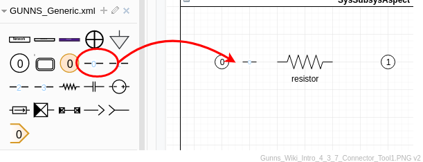
We drag a Link Port shape into the network container from the GUNNS_Generic.xml shape library:
Now we connect one end of the Link Port line to a node, and one to the link. If you have Options: Connection Points enabled in the Diagram pane (far right), which we recommend, then when you drag a line end near to a link or node, tiny blue x’s appear on them. These are recommended connection points on those shapes that you can connect to. Here we show a Link Port connected and still selected. Note the blue circles with x’s in them on the end-points — these mean a connection to a shape has been made:

You don’t have to connect to the connection points. You can make valid connections to nodes and links anywhere in their shape by hovering the Link Port end point over the shape until it highlights. Here we show the Link Port connected to the center of the node, and to an aribtrary point inside the link:

However, we recommend connecting to the designated connection points because it will look nicer.
Finally, we tell the Link Port which of the link’s ports it connects. This is the light-blue number label on top of the line. To change the number, select the line shape and simply type the desired number. The number label can be moved around by dragging its organge diamond-shaped anchor. Here we have changed the port number to 1 and moved its location:

Then we repeat for the link’s other ports to finish its connections.
The connector lines can be moved around, bends added to divert around other shapes as necessary. They can be formatted for line style and color for readability. The only thing GunnsDraw cares about is which node & link it connects and the port numbers.