Skip to content
New issue

Have a question about this project? Sign up for a free GitHub account to open an issue and contact its maintainers and the community.

By clicking “Sign up for GitHub”, you agree to our terms of service and privacy statement. We’ll occasionally send you account related emails.

Already on GitHub? Sign in to your account

Bug in drawing thick antialiased polylines #2183

Open
martincohen opened this issue Nov 12, 2018 · 12 comments
Open

Bug in drawing thick antialiased polylines #2183

martincohen opened this issue Nov 12, 2018 · 12 comments

Comments

@martincohen
Copy link

Version/Branch of Dear ImGui:
dear imgui, v1.66 WIP

Back-end file/Renderer/OS: (or specify if you are using a custom engine back-end)

Back-ends: imgui_impl_dx11.cpp + maybe others (haven't tested, but I expect the bug be in the imgui_draw.cpp)
OS: Windows 10

My Issue/Question: (please provide context)

Best described with image:
image

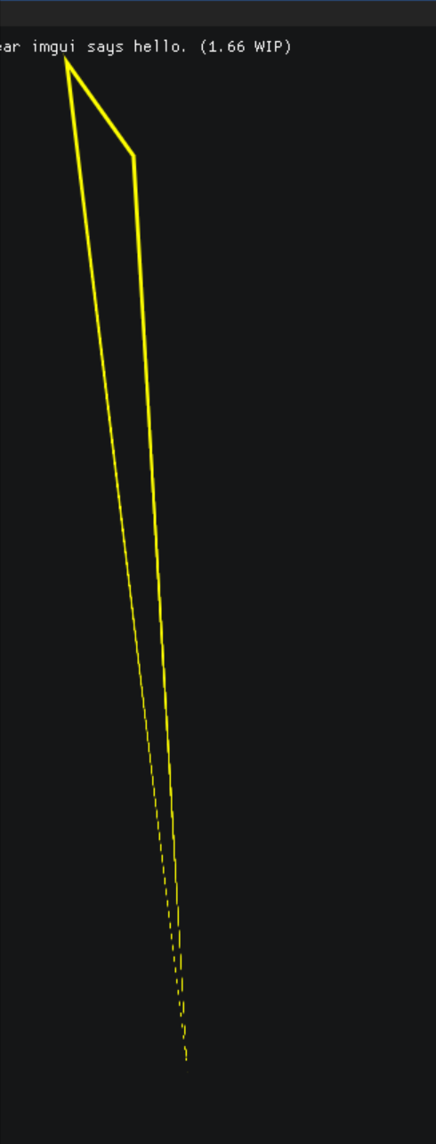
Without AA it seems to work as one would expect. Both thick lines (thickness > 1) and thin lines (thickness <= 1) are affected, also closed/not closed flag doesn't seem to have effect on this.

ImGui::Begin("Example Bug");
    static ImVec2 points[] = { { 100, 120 }, { 140, 800 }, { 50, 50 } };
    ImGui::GetWindowDrawList()->AddPolyline(points, 3, 0xFF00FFFF, true, 3.0f);
ImGui::End();
@ocornut ocornut changed the title Bug in drawing antialiased polylines Bug in drawing thick antialiased polylines Apr 29, 2019
@ce2kettu
Copy link

Has anyone addressed this issue/any workarounds? My application heavily depends on this feature and I might just look at nanovg or something for a custom implementation.

@ocornut
Copy link
Owner

ocornut commented Aug 16, 2019

Maybe @rmitton would have a suggestion?

@rmitton
Copy link
Contributor

rmitton commented Aug 21, 2019 via email

@ce2kettu
Copy link

ce2kettu commented Aug 23, 2019

As it stands out, I only need straight lines for my application, hence using anti-aliased lines is a waste of resources for me. I edited the non anti-aliased portion of ImDrawList::AddPolyline to include miter joints between line curves. Now my question is if there's a way to include a custom ImDrawList function without fiddling with the internal code, or how would you approach this situation? @ocornut

@ocornut
Copy link
Owner

ocornut commented Aug 23, 2019

Would your patch make sense as a PR ? May be useful as a reference even if not covering all cases.

Otherwise the lesser evil if to copy AddPolyLine() in your own code and call that version (it doesn't need to be inside the class, though you can create a dummy inheriting class with new method, cast and call, to benefit from the implicit this-> and minimize code drift).

@ce2kettu
Copy link

ce2kettu commented Sep 3, 2019

Sorry for the late reply, I was caught up with some stuff. I'll post the snippet here as a reference for those who might need it.

#define IM_NORMALIZE2F(VX, VY)         \
  {                                    \
    float d2 = VX * VX + VY * VY;      \
    float inv_len = 1.0f / ImSqrt(d2); \
    VX *= inv_len;                     \
    VY *= inv_len;                     \
  }

/* Draws a non-antialiased line with miter joint between curves */
void ImDrawList::AddPolylineMiter(const ImVec2* points, int num_points, ImU32 col, bool closed,
                                     float thickness) {
  int count = num_points;
  if (count < 2) return;

  const ImVec2 uv = _Data->TexUvWhitePixel;
  const int idx_count = count * 6;
  const int vtx_count = count * 4;
  PrimReserve(idx_count, vtx_count);

  for (int i1 = 0; i1 < count; i1++) {
    const int i2 = ((i1 - 1) < 0) ? 0 : (i1 - 1);
    const int i3 = ((i1 + 1) >= count) ? count - 1 : (i1 + 1);
    const int i4 = ((i1 + 2) >= count) ? count - 1 : (i1 + 2);
    const ImVec2& p0 = points[i2];
    const ImVec2& p1 = points[i1];
    const ImVec2& p2 = points[i3];
    const ImVec2& p3 = points[i4];

    // compute line segment
    float line_x = p2.x - p1.x;
    float line_y = p2.y - p1.y;
    IM_NORMALIZE2F(line_x, line_y);

    // find the normal vector of this line
    float normal_x = -line_y;
    float normal_y = line_x;
    IM_NORMALIZE2F(normal_x, normal_y);

    // find the tangent vector at both of the end points:
    // - if there are no segments before or after this one, use the line itself
    // - otherwise, add the two normalized lines and average them by normalizing again
    float tangent1_x, tangent1_y, tangent2_x, tangent2_y;
    if (p0.x == p1.x && p0.y == p1.y) {
      tangent1_x = line_x;
      tangent1_y = line_y;
    } else {
      tangent1_x = p1.x - p0.x;
      tangent1_y = p1.y - p0.y;
      IM_NORMALIZE2F(tangent1_x, tangent1_y);
      tangent1_x += line_x;
      tangent1_y += line_y;
      IM_NORMALIZE2F(tangent1_x, tangent1_y);
    }

    if (p2.x == p3.x && p2.y == p3.y) {
      tangent2_x = line_x;
      tangent2_y = line_y;
    } else {
      tangent2_x = p3.x - p2.x;
      tangent2_y = p3.y - p2.y;
      IM_NORMALIZE2F(tangent2_x, tangent2_y);
      tangent2_x += line_x;
      tangent2_y += line_y;
      IM_NORMALIZE2F(tangent2_x, tangent2_y);
    }

    // find the miter line
    float miter1_x = -tangent1_y;
    float miter1_y = tangent1_x;
    float miter2_x = -tangent2_y;
    float miter2_y = tangent2_x;

    // find length of miter by projecting the miter onto the normal
    float projection1 = normal_x * miter1_x + normal_y * miter1_y;
    float projection2 = normal_x * miter2_x + normal_y * miter2_y;
    float length1 = (thickness / projection1) * 0.5f;
    float length2 = (thickness / projection2) * 0.5f;

    _VtxWritePtr[0].pos.x = p1.x - length1 * miter1_x; _VtxWritePtr[0].pos.y = p1.y - length1 * miter1_y; _VtxWritePtr[0].uv = uv; _VtxWritePtr[0].col = col;
    _VtxWritePtr[1].pos.x = p2.x - length2 * miter2_x; _VtxWritePtr[1].pos.y = p2.y - length2 * miter2_y; _VtxWritePtr[1].uv = uv; _VtxWritePtr[1].col = col;
    _VtxWritePtr[2].pos.x = p2.x + length2 * miter2_x; _VtxWritePtr[2].pos.y = p2.y + length2 * miter2_y; _VtxWritePtr[2].uv = uv; _VtxWritePtr[2].col = col;
    _VtxWritePtr[3].pos.x = p1.x + length1 * miter1_x; _VtxWritePtr[3].pos.y = p1.y + length1 * miter1_y; _VtxWritePtr[3].uv = uv; _VtxWritePtr[3].col = col;
    _VtxWritePtr += 4;

    ImDrawIdx idx = (ImDrawIdx)_VtxCurrentIdx;
    _IdxWritePtr[0] = idx; _IdxWritePtr[1] = (ImDrawIdx)(idx + 1); _IdxWritePtr[2] = (ImDrawIdx)(idx + 2);
    _IdxWritePtr[3] = idx; _IdxWritePtr[4] = (ImDrawIdx)(idx + 2); _IdxWritePtr[5] = (ImDrawIdx)(idx + 3);
    _IdxWritePtr += 6;
    _VtxCurrentIdx += 4;
  }
}

@nem0
Copy link
Contributor

nem0 commented Oct 24, 2019

Continuing #2868 here

Possible fix with no additional sqrt, place here:

const int i2 = (i1+1) == points_count ? 0 : i1+1;

for (int i1 = 0; i1 < count; i1++)
{
    const int i2 = (i1+1) == points_count ? 0 : i1+1;
    unsigned int idx2 = (i1+1) == points_count ? _VtxCurrentIdx : idx1+4;

    // Average normals
    float dm_x = (temp_normals[i1].x + temp_normals[i2].x) * 0.5f;
    float dm_y = (temp_normals[i1].y + temp_normals[i2].y) * 0.5f;

    // direction of 1st edge
    float v0x = -temp_normals[i1].y;
    float v0y = temp_normals[i1].x;

    // project direction of 1st edge on 2nd edge normal
    float dot = v0x * temp_normals[i2].x + v0y * temp_normals[i2].y;

    // -direction of 2nd edge
    float v1x = temp_normals[i2].y;
    float v1y = -temp_normals[i2].x;

    // scale 
    dm_x = (v0x + v1x) / dot;
    dm_y = (v0y + v1y) / dot;
                
    //IM_FIXNORMAL2F(dm_x, dm_y);
    float dm_out_x = dm_x * (half_inner_thickness + AA_SIZE);
    float dm_out_y = dm_y * (half_inner_thickness + AA_SIZE);
    float dm_in_x = dm_x * half_inner_thickness;
    float dm_in_y = dm_y * half_inner_thickness;

    // Add temporary vertexes
    ImVec2* out_vtx = &temp_points[i2*4];
    out_vtx[0].x = poin

@Omegastick
Copy link

@nem0 That code does seem to fix the mitre issue, but misses off the final segment of the line.

See the picture below:
image
The right half of the check mark is and the final segment of the plot is gone.

I'll have a look and see if I can fix it.

@Omegastick
Copy link

Omegastick commented Nov 2, 2019

I feel like there's a better way to do it (the math goes a bit over my head here) but I made it work:

for (int i1 = 0; i1 < count; i1++)
{
    const int i2 = (i1+1) == points_count ? 0 : i1+1;
    unsigned int idx2 = (i1+1) == points_count ? _VtxCurrentIdx : idx1+4;
     // Average normals
    float dm_x = (temp_normals[i1].x + temp_normals[i2].x) * 0.5f;
    float dm_y = (temp_normals[i1].y + temp_normals[i2].y) * 0.5f;

    // Direction of 1st edge
    float v0x = -temp_normals[i1].y;
    float v0y = temp_normals[i1].x;

    // Project direction of first edge on second edge normal
    if (closed || i2 != count)
    {
        float dot = v0x * temp_normals[i2].x + v0y * temp_normals[i2].y;
        // Negative direction of 2nd edge
        float v1x = temp_normals[i2].y;
        float v1y = -temp_normals[i2].x;

        // Scale 
        dm_x = (v0x + v1x) / dot;
        dm_y = (v0y + v1y) / dot;
    }
    else
    {
        IM_FIXNORMAL2F(dm_x, dm_y);
    }

image

As you can see from the big spike at the bottom of the graph, sometimes the generated mitre is very big, but that's a necessary part of the algorithm, I guess. Rounded corners would need too many polygons, I presume.

@ocornut, I can make a PR if you'd like.

Omegastick pushed a commit to Omegastick/imgui that referenced this issue Nov 2, 2019
@nem0
Copy link
Contributor

nem0 commented Nov 3, 2019

@Omegastick I checked only closed polylines. To fix the nonclosed polylines, add:

				if (!closed && i1 == count - 1) {
					dm_x = temp_normals[i2].x;
					dm_y = temp_normals[i2].y;
				}

before

float dm_out_x = dm_x * (half_inner_thickness + AA_SIZE);

@nem0
Copy link
Contributor

nem0 commented Nov 3, 2019

The big mitre can be easily fixed easily, while introducing just one more vertex
image
The price is more complex drawing code. I did not bother with it since I don't min the big mitre.

@ocornut
Copy link
Owner

ocornut commented Apr 19, 2021

A bug was fixed today, see my post
#4053 (comment)

@martincohen : the bug fix unfortunately doesn't fix the exact issue outlined in your initial post (it should look exactly as your screenshot above, note that before today's fix it looked worse), but as the post was made just before another bug was introduced and most discussions happened after that bug was introduced, things got confusing. However while fixing I've understood the how raising our scaling limit essentially "fixes" your triangle (in concrete term raising the IM_FIXNORMAL2F_MAX_INVLEN2 value from x100 to x500 or even FLT_MAX).

@nem0 @Omegastick
Testing your version (without following the maths) and comparing it seems equivalent to the current (= just pushed) code except for the x100.0f scaling limit for which I expected the reasoning in the post linked above.

Without the scaling limit: (notice the red circle is the provided point)
image
The scaling limit is "incorrect" and is the cause for thickness loss in acute cases, but it also prevents create the issue of polygons straying out of expected boundaries too much, which is in the case of e.g. plots can be very problematic. I expect us to provide the option of either using miter either lifting the scaling limit (via a flag).
Bound to clarify that the a fair share of the problem you were experiencing while writing those comment may be fixed by #4053 already.

(
Anecdotally: I have experimented with moving the thickness polygons inward instead of centering it around the provided points.

    1. it would creates a requirement that shapes are clockwise (could accept that limitation)
    1. doesn't even guarantee that the polygons geometry stays close to provided points by half-thickness (so doesn't really solve our problem)
  • 2.1) it generally only makes sense for closed shapes especially when convex-ish
  • 2.2) therefore would lead to abrupt changes between closed and unclosed shapes
    So I ditched this idea.
    )

TL;DR; need some kind of miter (opt-in and configurable)

Sign up for free to join this conversation on GitHub. Already have an account? Sign in to comment
Projects
None yet
Development

No branches or pull requests

6 participants