Releases: rgoulter/keyboard-labs
PyKey40 Lite
This is my first PCBA design.
Takes jpconstantineau's PyKey60, and arranges a no-frills (no RGB, no hotswap, no speaker) subset of it to be a drop in replacement for the BM40/JJ40 PCB.
CAD files are also provided so you can lasercut switch plates or cheap case plates.
Errata
-
Although I've observed that the PCB works properly when the switches are soldered in, I've observed that before switches are soldered in, shorting the pads makes it look like multiple switches in the same column are pressed(!!). e.g. short
SW_2_2, thenSW_2_3will also appear shorted to the keyboard. -
The position for J1 (USB-C connector) isn't quite right. When I've ordered from PCBA, the DFM Check picks this up and fixes this without complaint.
-
The kicad_pcb DRC raises concerns about U1 (RP2040 MCU) annular width. This wasn't an issue in the PCBs I've had fabricated.
-
The kicad_pcb DRC raises the error "Thermal relief connection to zone incomplete". In the PCBs I've had fabricated, I haven't found this to be a problem.
Assets
If you want to order these, it's assumed you'll use JLCPCB. (The kicad_pcb uses "JLCJLCJLCJLC" to indicate where the manufacturer can put the order number).
To fabricate the PCBA:
keyboard-pykey40-lite-gerber_zip.zipis the gerber zip.keyboard-pykey40-lite_bom_jlc.csvis the BOM CSV.keyboard-pykey40-lite_cpl_jlc_bottom_pos.csvis the BOM/position file.
X-2 HSRGB (Lumberjack-inspired ARM, Ortholinear 5x12, HotSwap, RGB) Keyboard, rev2022.1
peej's lumberjack-keyboard is a cool and creative
design, which continues the style of "show the components" used by keyboards like
the plaid.
One downside to it is that DIP microcontrollers aren't quite powerful enough to power every bell & whistle that QMK has to offer. Development boards are a spiritual-successor to DIP microcontrollers, so I wanted to adapt the striking Lumberjack design to a more powerful development board.
The X-2 HSRGB is fancier version of the X-2. With all the benefits of the X-2 (fits in GH-60 case, powerful microcontroller),
but with a RGB lighting, which makes the keyboard a bit fancier.
Design goals:
- Same as X-2:
- Using STM32 dev board. (ARM-powered!).
- Adapt the Lumberjack design.
- In a "show the components" style.
- Fits in tray-mount GH60 case.
- (Relatively) easy to solder.
- Additional fancy features:
- HotSwap: the PCB uses Kailh's MX Hotswap sockets. This allows being able to swap out which switches
are used by the keyboard, without needing to resolder (or resort to using PCB rivets). - RGB lighting: the PCB allows for putting RGB lights under each key, as well as RGB underglow.
- HotSwap: the PCB uses Kailh's MX Hotswap sockets. This allows being able to swap out which switches
The PCB can be assembled with either MX-compatible or Kailh Choc v1 switches. The ARM devboard can be either a Bluepill, or a WeAct Studio MiniF4 "Blackpill".
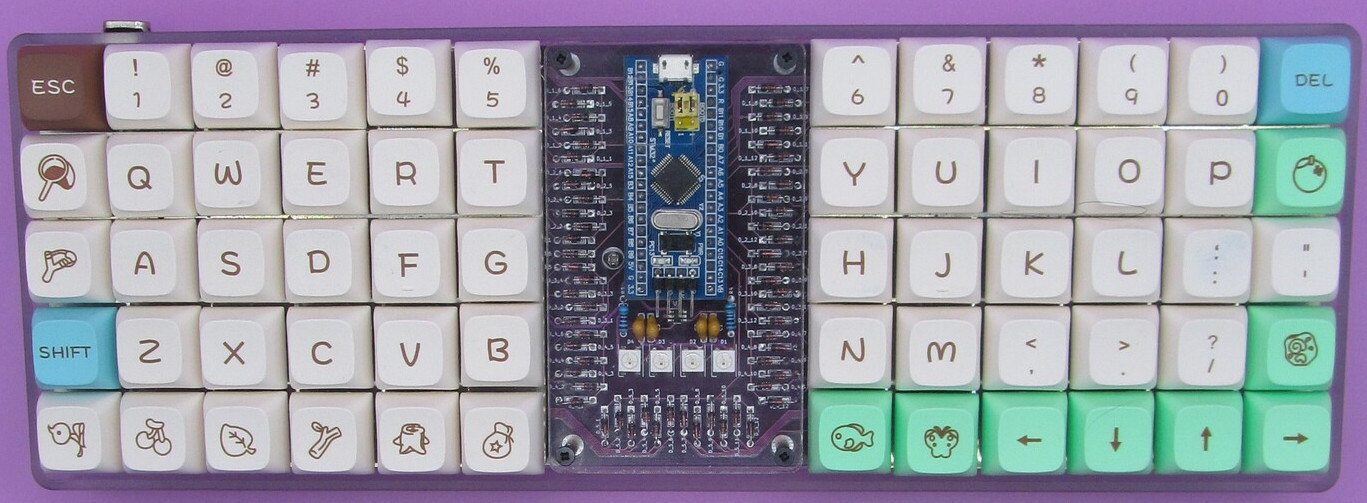
X-2 HSRGB PCB assembled, using a Bluepill devboard, with MX switches, in a cheap GH-60 case.
Assets:
- Gerber files in zip, suitable for sending to a PCB manufacturer.
- Note: e.g. JLCPCB requested additional charges to fabricate the PCB, due to the additional setup time that the PCB requires.
- Lasercutting files:
- cover: acrylic cover for the middle of the keyboard. "mcu-blackpill" and "mcu-bluepill" have a hole cut out so the devboard's reset buttons can be accessed. Recommended material: 3mm acrylic.
- plate-switch: for switch plates for the key switches. Recommended material: 1.5mm metal (e.g. stainless steel) for MX switches, 1mm for Choc switches.
X-1 (MiniF4-36, sub-100x100mm 36-key featureful split keyboard), rev2021.5
The X-1 (MiniF4-36) is a 36-key split keyboard with the following design goals:
- PCB smaller than 100x100 mm2, so that it's cheaper to fabricate at various PCB fabricators.
- Reversible PCB (use the same PCB for left/right halves).
- Using the WeAct Studio MiniF4 "black pill" dev board, a cheap STM32F4 dev board that runs ARM.
- Low profile (PCB + choc switches + bumpons).
- Column-staggered arrangement of key switches.
- Fancy features: e.g. per-key RGB LEDs, rotary encoders, OLED screen, DC vibration motors.
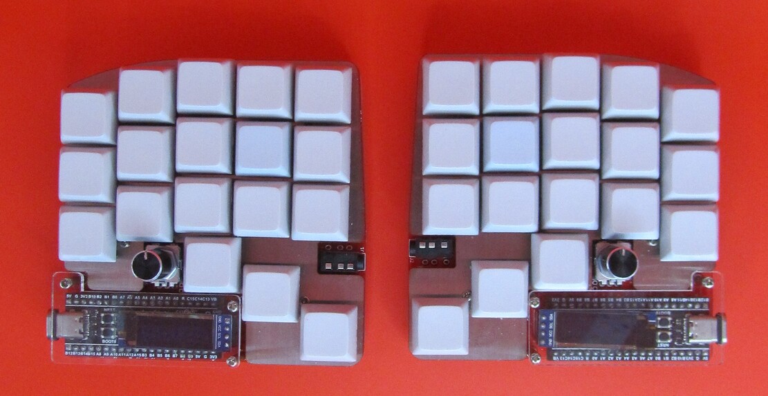
X-1, rev2021.5, MX variation (with rotary encoder, OLED, etc.).
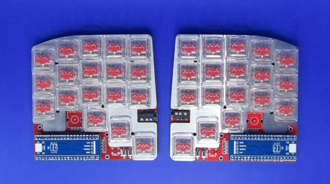
X-1, rev2021.5, Choc variation, low-profile (with flipped GD-32 Bluepill devboards).
Height comparison between low-profile build (with Choc switches) and with sandwich-case.
Tented.
Showing the underside of the PCB through the acrylic bottom layer.
2D Renders of the PCB, revision rev2021.5
Schematic: keyboard-100x100-minif4-dual-rgb-reversible-schematic.pdf
CSV BOM: keyboard-100x100-minif4-dual-rgb-reversible-bom.csv
Assets:
- Gerber is in the zip file, suitable for sending to PCB manufacturers.
- Lasercutting files (SVG or DXF):
- cover: top cover for the microcontroller devboard, either with a hole which allows access to the reset buttons, or without.
- top plate: switch plate. Recommended material: 1.5mm metal (e.g. stainless steel) for MX switches, 1mm metal for Choc switches.
- bottom plate: either with holes cut to allow room for a small DC motor (and reset buttons) mounted underneath the PCB, or a simple bottom plate. Recommend material: 3mm acrylic.
X-2 (Lumberjack-inspired ARM, Ortholinear 5x12) Keyboard, rev2021.1
peej's lumberjack-keyboard is a cool and creative
design, which continues the style of "show the components" used by keyboards like
the plaid.
One downside to it is that DIP microcontrollers aren't quite powerful enough to power every bell & whistle that QMK has to offer. Development boards are a spiritual-successor to DIP microcontrollers, so I wanted to adapt the striking Lumberjack design to a more powerful development board.
Design goals:
- Using STM32 dev board. (ARM-powered!).
- Adapt the Lumberjack design.
- In a "show the components" style.
- Fits in tray-mount GH60 case.
- (Relatively) easy to solder.
The PCB can be assembled with either MX-compatible or Kailh Choc v1 switches. The ARM devboard can be either a Bluepill, or a WeAct Studio MiniF4 "Blackpill".
X-2 PCB assembled, using a Bluepill devboard, with MX switches, in a cheap GH-60 case.
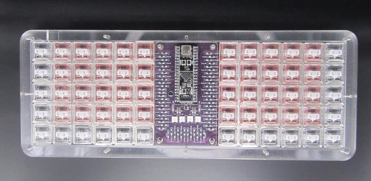
X-2 PCB assembled, using a WeAct Studio MiniF4 "Blackpill" devboard, with Choc switches, in a layered acrylic case.
2D Renders of the PCB, revision rev2022.1
Schematic: keyboard-x2-lumberjack-arm.pdf

Interactive BOM: rev2021.1 Interactive BOM
Assets:
- Gerber files in zip, suitable for sending to a PCB manufacturer.
- Lasercutting files:
- cover: acrylic cover for the middle of the keyboard. "mcu-blackpill" and "mcu-bluepill" have a hole cut out so the devboard's reset buttons can be accessed. Recommended material: 3mm acrylic.
- plate-switch: for switch plates for the key switches. Recommended material: 1.5mm metal (e.g. stainless steel) for MX switches, 1mm for Choc switches.
v2021.4
v2021.3
v2021.2
- Fix issues from rev2021.1:
- Add SN74LVC1T45DBV so that SK6812mini-e and SK6812
get 5V data signal from minif4. - Fix schematic for pins PA2, PB9, PC15 to align with firmware for (jumped) rev2020.1 board.
- Add SN74LVC1T45DBV so that SK6812mini-e and SK6812
- Use updated minif4 footprint.
(i.e. without the redundant 5V/GND/3V3). - Simplify reference designators.
e.g. from J_r_1 to J_2, R_LED_1 to R4, etc. - Add TP_1, TP_2 01x04 connection pins
to breakout pins. Allows using other controller to
test the RGB LEDs, or using the board to test other
RGB LED strips. - Add PCB artwork.
Kicad: update PCB for keyboard 100x100 minif4 36-key
Changelog:
- Update per the schematic:
- e.g. fix issue from rev2021.1:
- add LVC,
- adjust position of top-right hole for M2 spacer.
- add breakout pins for RGB in/out.
- use the other 5V, 3V3, GND pins of the minif4.
- e.g. fix issue from rev2021.1:
- Use thinner traces for signal traces.
- Route so as to maximize the GND zone fill on back copper layer,
try keep signal traces far apart.
v2021.2 (Fab'd on 03/03)
Design sent for fabrication on 2021-03-03, with silkscreen labeling it as "v2021.2".
Fabrication status: fabricated, received PCBs.
v2021.1
PCB: Sub-100x100mm 36-key MiniF4 Split Keyboard
PCB design for a sub-100x100, split, 36-key keyboard using the WeAct Studio MiniF4 "black pill" dev board.
Fabrication Status
- UPDATE: 2021/03/08: received PCBs for this revision. Upon testing the assembled PCBs, noticed the schematic was accidentally different from rev2020.1.
Changes from rev2020.1
- MiniF4 footprint now uses zig-zagged column of pins.
- Changed the layout of the thumb keys.
- Switch footprint now supports both MX and Choc switches.
- Added RGB underglow.
- Added simpler PCB variations (MX-only, Choc-only, with or without RGB lighting).
- Added Kicad files for bottom plate and switch plate. Holes added in PCB to support M2 spacers and screws.
- FIX: change the switch/pin assignments per errata noted in rev2020.1. (N.B.: pin assignment different than rev2020.1. Notably, C15 is used for SW_15 and A2 for SW_31. - This does affect e.g. micropython repl, the pin PC15 is always low when the
mpconfigboard.hused the RTC, as it does by default i.e.#define MICROPY_HW_ENABLE_RTC (1)).
Errata
- The design of the circuit for the SK6812mini-e and SK6812 LEDs is invalid. i.e. the RGB LEDs don't work. The VDD the SK6812mini-e receive is from the
3V3pin. This is insufficient to power the RGB LEDs. TheDINfromA0has the same3V3voltage, and so can't reliably signal the series of RGB LEDs. - The location for the M2 spacer in the top-right of the PCB (top left for the reverse side) is slightly too high. It would be better if it were equidistant between the switch above/below it.
Files for Switch Plate, Bottom Plate
SVGs for laser-cutting:
- Switch plate:
keyboard-100x100-minif4-plate_top-reversible-Dwgs_User.svgwas manually edited in Inkspace after plotting theDwgs-Userlayer of the Kicad PCB. - Bottom plate:
keyboard-100x100-minif4-plate_bottom-reversible-Dwgs_User.svgis theDwgs-Userlayer plotted as SVG.
PCB: Soldering Practice PCBs
Small PCBs which can be used to practice soldering the RGB LEDs.
Errata
- Similar to the mistake in the keyboard PCB: the silkscreen incorrectly labels VDD as
3V3. - The arrangement of pins in this design (left to right) is
VDD, GND, DIN, DOUT. In Adafruit NeoPixel modules (and clones), the pin layout isGND, VDD, DIN, GNDon one end, running straight through toGND, VDD, DOUT, GND. If the same arrangement were used, the same breadboard could be used with both an Adafruit NeoPixel module (as a control) and these soldering practice PCBs.
v2020.1
Initial release of the PCB design for this split, 36-key keyboard.
Design goals:
- PCB smaller than 100x100 mm2, so that it's cheaper to fabricate at various PCB fabricators.
- Reversible PCB (use the same PCB for left/right halves).
- Using the WeAct Studio MiniF4 "black pill" dev board.
- Low profile (PCB + choc switches + bumpons).
- Column-staggered arrangement of key switches.
- Per-key RGB LEDs.
Errata:
- Pins PA11, PA12, PB2 aren't suitable for use for GPIO on the MiniF4 board, since these are used for other things. This can be mitigated by jumping from PTHs underneath unused pins of the devboard.
- The design of the circuit for the SK6812mini-e LEDs is invalid. i.e. the RGB LEDs don't work. The VDD the SK6812mini-e receive is from the
3V3pin. This is insufficient to power the RGB LEDs. TheDINfromA0has the same3V3voltage, and so can't reliably signal the series of RGB LEDs.


