Programming an STM32F103XXX with a generic "ST Link V2" programmer from Linux
The following was tested on an Ubuntu Linux (14.10) box, so your mileage may vary if you are using some other platform.
I used a clone "ST-Link V2" device and OpenOCD, the genuine ST-Link adapters would presumably work just as well if not better.
The OpenOCD version used in my testing was "Open On-Chip Debugger 0.9.0-dev-00401-gf3b1405 (2015-04-16-12:04)" which is fairly bleeding edge. Earlier versions may work, however I would suggest going for something recent.
This is an alternative method for programming the STM32F103XXX series devices, and any others that support ST-Link. ST-Link also allows On Chip debugging and direct access to the resources of the processor, so it is a very powerful debug tool. I will only cover programming the STM32F103XXX here - refer to the OpenOCD documentation at http://openocd.org/ for more in depth insight into the scope of OpenOCD debugging. OpenOCD can also be used with the Eclipse IDE, and perhaps other IDEs.
You will probably find in most cases it easier to use a USB to serial converter or install the maple boot loader and use dfu-util if you simply want to write a sketch to the board.
This method is a work in progress, so expect these instruction to be incomplete, I am jotting them down before I forget what I did.
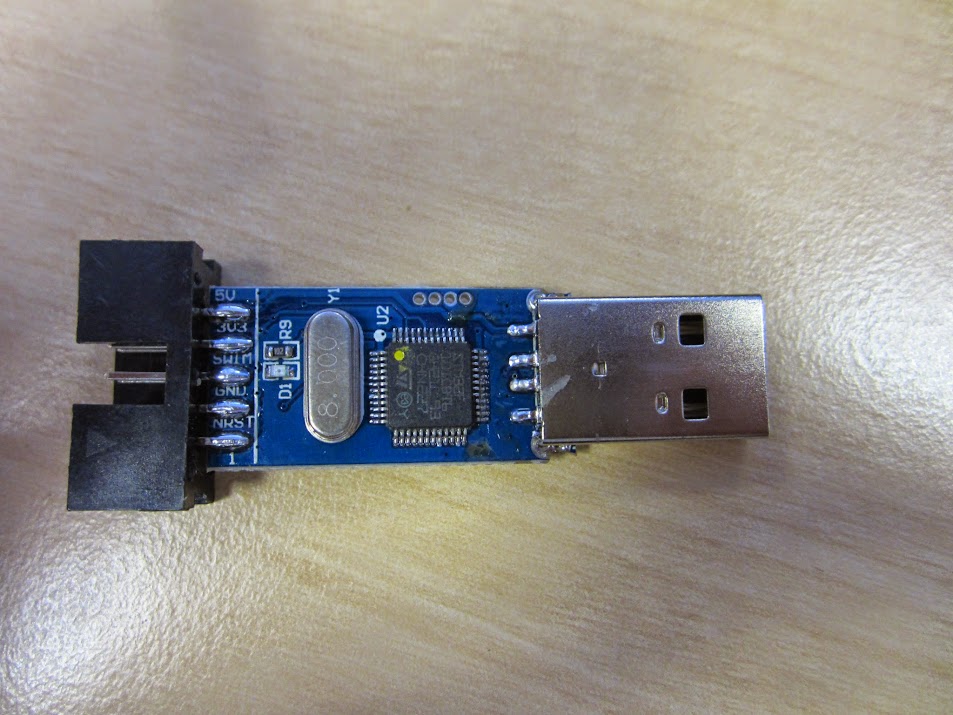
First take the new ST-Link clone and plug it in to one of your USB ports. These little boards are very cheap, possibly even cheaper than a usb serial adapter.
Look in dmesg and you should see something like this...
[ 3377.046983] usb 1-1.5.3.3: USB disconnect, device number 11
[ 3439.715490] usb 1-1.5.3.3: new full-speed USB device number 12 using ehci-pci
[ 3439.826110] usb 1-1.5.3.3: New USB device found, idVendor=0483, idProduct=3748
[ 3439.826120] usb 1-1.5.3.3: New USB device strings: Mfr=1, Product=2, SerialNumber=3
[ 3439.826125] usb 1-1.5.3.3: Product: STM32 STLink
[ 3439.826129] usb 1-1.5.3.3: Manufacturer: STMicroelectronics
[ 3439.826133] usb 1-1.5.3.3: SerialNumber: R\xffffffc3\xffffffbf\xffffffbfo\x06Q\xffffffc2\xffffff88\xffffff88QTQ)"g
Next, wire the board up to the target. The pins used may be less than obvious, I went for the minimum, and used my Yellow Headers STM32 board, which looks like this...

.. I used this partly because it didn't have an STM JTAG header on it, and I like to make life difficult for myself, but mainly because the other boards were at home.
I wired it as per the pictures here, having figured out that the pins I needed for jtag were probably on the right angled header...
The Programmer end was wired like this...

... and here is the target board end...

... and here is another STM32F103C8T6 board wired to the JTAG header for comparison. Note the dangling orange wire, as I am powering this board from USB. Also worth mentioning are the three wires leaving the picture at the bottom right which are attached to a servo, and have nothing to do with the programmer.

.. and a few more related pictures can be found here...
WARNING: When developing, and powering the STM target board from the programmer, if you intend to plug in the USB port at the same time, then remove the power (orange) wire first, and power the board from USB otherwise you may see some magic smoke.
The logic behind the wiring may be unclear, so I'll explain.
We need 3 wires for basic ST-Link functionality, the actual colours of the wires are not important. I went for...
Programmer -> Target
Ground (Green) -> GND
SWDIO (Blue) -> PA13 (D22 on Maple Mini)
SWCLK (Yellow) -> PA14 (D21 on Maple Mini)
The exact location of these pins on your test board will perhaps be less than obvious, particularly since the pins on the STM32 are multifunctional, so refer to the STM datasheet around page 32 and the schematic for your board for more information.
In addition if you want to power the board under test from the ST-Link programmer, connect either +5v or +3v3, this is the Orange wire in the pictures. You don't need this wire if you are powering the board you are programming from USB or some other source.
I had previously installed openocd from the Ubuntu repos, but this was a relatively out of date version. I like to live dangerously and decided to use the latest version from the GIT repo.
The following recipe did the trick for me....
Remove any old version of openocd
sudo apt-get remove openocd
unset CXX
NOTE: This unset command is optional, but perhaps necessary if you have been using cross compilers from the command line. I have been compiling for the Raspbery Pi on my machine, and unless I do this I get the wrong compiler.
Next create a folder to put the openocd git repo in
mkdir -p ~/sandbox
cd ~/sandbox
mkdir openocd
git clone git://repo.or.cz/openocd.git
cd openocd
sudo apt-get install make libtool pkg-config autoconf automake texinfo libusb-1.0-0-dev
./bootstrap
./configure
make
sudo make install
Check that openocd runs and if so, we can move on...
Next we need to run openocd, but since I had no clue how this works, I opted to run it in a bash loop using the default config files that ship with openocd....
while true; do openocd -f /usr/local/share/openocd/scripts/interface/stlink-v2.cfg -f /usr/local/share/openocd/scripts/target/stm32f1x.cfg ; sleep 1;done
.. I'll come back to this once I have figured out how to do this correctly.
In another terminal window we telnet to the openocd console on port 4444
telnet localhost 4444
Now while that is running, we need to do a couple of things in the correct order
Press and hold the reset button on the target....
In the telnet session issue a reset halt command.
> reset halt
timed out while waiting for target halted TARGET: stm32f1x.cpu - Not halted in procedure 'reset' in procedure 'ocd_bouncer' ...
... release the reset button.. target should halt after reset...
... target state: halted target halted due to debug-request, current mode: Thread xPSR: 0x01000000 pc: 0x0800016c msp: 0x20005000 ...
Bingo... we have control..
.. so what's the first thing we need to do... dump the existing firmware of course...
> dump_image dump.bin 0x08000000 0x1ffff
dumped 131071 bytes in 2.825877s (45.295 KiB/s) **> **
We have complete control, so we can now program the device... so why not flash the maple bootloader on it?
Grab a suitable bootloader for the board from here..
https://github.com/rogerclarkmelbourne/STM32duino-bootloader/tree/master/binaries
Then upload it to the device... halt it first...
> reset halt
target state: halted **target halted due to debug-request, current mode: Thread ** xPSR: 0x01000000 pc: 0x0800016c msp: 0x20005000
NOTE: If the chip flash is protected, you may also need to issue a "stm32f1x unlock" command.
> flash write_image erase maple_mini_boot.bin 0x08000000
auto erase enabled
target state: halted **target halted due to breakpoint, current mode: Thread ** xPSR: 0x61000000 pc: 0x2000003a msp: 0x20005000
wrote 16384 bytes from file maple_mini_boot.bin in 0.949075s (16.859 KiB/s)
Success! So now restart the device...
> reset run
Now if you unplug and replug the device in to a USB port and look in dmesg...
[95669.294185] usb 1-1.2: new full-speed USB device number 34 using ehci-pci [95669.387630] usb 1-1.2: New USB device found, idVendor=1eaf, idProduct=0003 [95669.387634] usb 1-1.2: New USB device strings: Mfr=1, Product=2, SerialNumber=3 [95669.387636] usb 1-1.2: Product: Maple 003 [95669.387637] usb 1-1.2: Manufacturer: LeafLabs [95669.387638] usb 1-1.2: SerialNumber: LLM 003
... you should see the Maple Leaflabs device enumarated... its running our code!
If you made it this far, congratulations you now have total control over the STM device, you can reflash, reformat, reprogram, debug, or do whatever you want to it.