Tutorial 1: rftest1
Let's start our testing scenario. We will show the network we're simulating and walk you through the testing script for rftest1. It's a basic scenario that contains the essencial steps to create a RouteFlow network, and can be expanded for more complex setups.
We are simulating the following scenario:
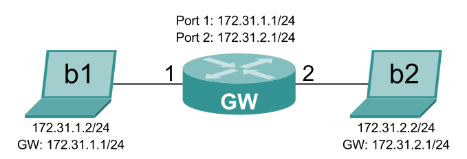
There are two hosts, b1 and b2, connected to a gateway. This gateway will be the OpenFlow switch acting as a router.
In RouteFlow a virtual machine represents an OpenFlow switch. Whatever happens with the routing and ARP tables of this virtual machine is replicated in the switch. The RFClient is responsible for listening to events in these tables and informing the RFServer.
For our purposes, we will employ an LXC container, a lightweight virtualization solution.
You can check the parts that we will customize in the default LXC container.
In order for our switch to behave as a gateway, connecting two hosts in two different subnetworks, it needs to have two interfaces, one in each network:
auto lo
iface lo inet loopback

auto eth0
iface eth0 inet static
    address 192.169.1.100
    netmask 255.255.255.0

auto eth1
iface eth1 inet static
    address 172.31.1.1
    netmask 255.255.255.0

auto eth2
iface eth2 inet static
    address 172.31.2.1
    netmask 255.255.255.0
The interfaces that matter to us are:
-
eth0: The management interface that will connect the RFClient instance to the rest of the RouteFlow architecture. -
eth1: The first interface, representing port 1 of the OpenFlow switch, connected to hostb1 -
eth2: The second interface, representing port 2 of the OpenFlow switch, connected to hostb2
The config file will declare the interfaces we need in LXC:
lxc.utsname = rfvm1
lxc.network.type = veth
lxc.network.flags = up
lxc.network.hwaddr = 12:a0:a0:a0:a0:a0
lxc.network.link=lxcbr0

lxc.network.type = veth
lxc.network.flags = up
lxc.network.veth.pair = rfvm1.1
lxc.network.hwaddr = 12:a1:a1:a1:a1:a1

lxc.network.type = veth
lxc.network.flags = up
lxc.network.veth.pair = rfvm1.2
lxc.network.hwaddr = 12:a2:a2:a2:a2:a2
...
lxc.rootfs = /var/lib/lxc/rfvm1/rootfs
lxc.mount  = /var/lib/lxc/rfvm1/fstab
...
This should be standard for all setups. The names and hardware address will need to be changed for different setups. The hardware address for the first interface (rfvm1.0) will be used as the ID of the RFClient instance. In this case, it will be 12A0A0A0A0A0. The rootfs and mount properties also have to be consistent with the location of the container (it will usually be /var/lib/lxc).
We will also enable IPv4 forwarding in /etc/sysctl.conf so that rfvm1 will behave as a gateway and disable Quagga since it's installed by default but we won't be using it for this specific scenario. These changes are visible in their respective files and should be easy to understand.
The /etc/rc.local is also configured to always call a script to start the RFClient instance in /root/run_rfclient.sh.
All these customizations, when structured like in the rftest/config/rfvm1 folder will be read the the rftest/create script, that will create any number of LXC containers based on a basic template. You can read more about that in the virtual environment creation page.
A few things to know about the rftest1 script:
- Everything must be executed as root
- There's function called
wait_port_listenthat blocks execution until a socket starts listening on a given port. - And there's another function, called
reset, that clears everything up before a test. We'll detail later which steps this funcions takes. - There are a couple other functions in the script, but they are there to help the other or provide pretty output.
The first thing we want to do is reset our testing environment, to clear anything that might have happened in previous runs and would interfere with our current run. For that, we will call our reset function, with 1 as its argument, indicating that we are starting the script.
We will also trap a the INT signal, so that our script closes and clears everything when we press CTRL+C.
Then we configure the lxcbr0 bridge. It will be responsible for connecting the management interfaces of the LXC containers.
After that's done, the MongoDB server is configured to listen on this bridge, so the LXC containers can connect to the RouteFlow architecture.
And now, we go on to the interesting part.
Now we need to configure the rfvm1 LXC container that will run as our RFClient. The steps that are taken to ensure that rfvm1 is ready to run RFClient:
- Create a directory and place the RFClient program there
- Copy the MongoDB client drivers so that RFClient the can use them.
- Create a script to start RFClient.
The script created in step 3 is something like this:
#!/bin/sh
sleep 5
/opt/rfclient/rfclient > /var/log/rfclient.log
It sleeps for a few seconds, waiting for the interfaces to go up, and then runs RFClient. The output will be sent to the /var/log/rfclient.log file. So, if you think RFClient is the cause of your problems, take a look in there.
This script is configured to be called during boot, in the /etc/rc.local file.
Once the container is configured, we start it.
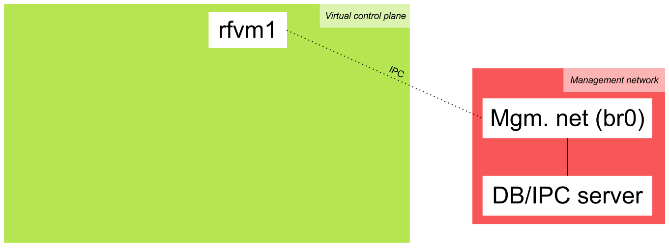
Now we need a way to connect the containers to our host that is running the database server. For that we will create an Open vSwitch bridge, connecting the management interfaces in the containers to our host system (in this case, only eth0 in rfvm1). We give this bridge the name br0 and the address 192.169.1.1 at the host.
This address is hardcoded in
rflib/defs.hfor the RFClient and the NOX version of RFProxy, andrflib/defs.pyfor RFServer and the POX version of RFProxy. This is not how it should be, and we make this a command-line argument in the future. For now, if you need to change it, you will have to mess with these files.
For now, this is what our setup looks like:
Now we need to start the controller we want. Along with the controller, we will start the RFProxy application, that's just a common application in the controllers. For now, there's only support a POX RFProxy. Floodlight and Ryu support are coming soon, and the the NOX implementation is deprecated.
We ask the log level to be INFO, so that the user is informed of interesting events when learning about RouteFlow. You can change that if you want more or less messages.
Now we wait for the controller to start listening, and then we will start the RFServer. For the RFServer we need a configuration file, telling RouteFlow how to map the virtual environment to the physical one.
For rftest1, this file looks like this:
vm_id,vm_port,ct_id,dp_id,dp_port
12A0A0A0A0A0,1,0,99,1
12A0A0A0A0A0,2,0,99,2
The first line is there just to make it more readable. What matters are the other ones. The first one, for example, says this:
"Map interface 1 (typically eth1) of RFClient with ID 12A0A0A0A0A0 to port 1 of the switch with datapath ID 99."
The 0 in the middle (
ct_id) indicates which controller instance the switch will be connected to. It's a feature to support multiple controllers, each controlling part of a network. It's still not very well documented and usable. If you need or want to use this, contact us and we will help you :) If that's not the case, just use 0 and ignore it.
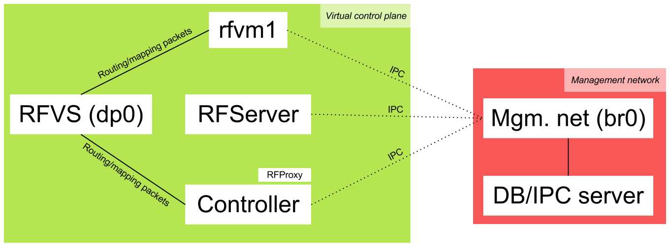
Once we've started RFServer, we need to establish a fast link between the controller and all of the containers interfaces, except the control interface (eth0).
This is done so that ARP, ICMP and routing packets (OSFP, BGP, RIP...) are directly forwarded to the RFClient instances running in the containers, without the need to go through RFServer. However, RFServer controls this link. By default, whenever a RFClient instance is associated with a switch, it will allow this forwarding to happen. This links is implemented using a bridge called the RouteFlow virtual switch (RFVS).
We will use an Open vSwitch bridge as our RFVS. Its name is dp0 and its datapath ID is 7266767372667673 (RFVSRFVS in ASCII hex encoding :). Any datapath ID starting with 72667673 will be considered an RFVS, and you can have any number of RFVS. We need to connect it to our controller (at tcp:127.0.0.1:6633 in our case), that will be responsible for forwarding packets between the data plane (switches) and the virtual control plane (containers).
When a physical-to-virtual, switch-to-RFClient match is made, RFServer instructs the RFClient instance to send a specific mapping packet through its interfaces that will go through the RFVS and arrive at the RFProxy. Once that happens, RFProxy informs RFServer about how the RFClient instance is connected to the RFVS. By default, RFServer will configure RFProxy to forward packets between that RFClient instance and the switch to which it's associated. This control is part of the RouteFlow architecture, since the RFServer is supposed to be a central point for controlling the network.
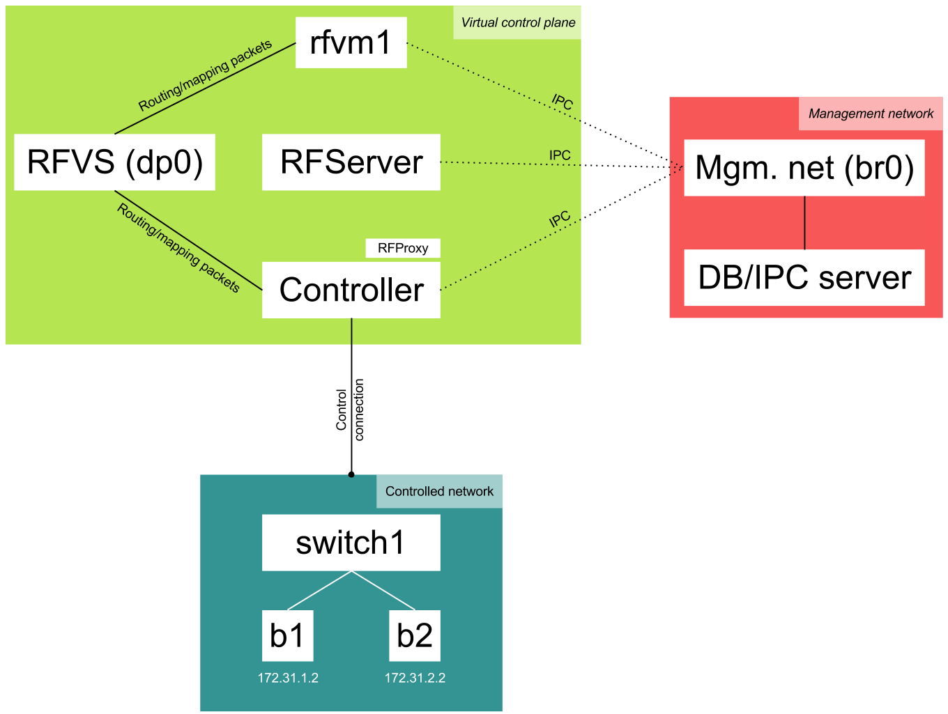
Now RouteFlow is ready. It's time to start our network. The setup looks like this now:
To make thinks simpler for everyone, we will simulate a virtual network and hosts :) However, we could as well be using a hardware switch and physical hosts for this.
The virtual hosts, b1 and b2, were created with the default testing environment as LXC containers. We start them and create an Open vSwitch virtual switch, setting its name to switch1 and its datapath ID to 99. Then we set the ports that connect it to our virtual hosts (b1 and b2) and instruct it to connect to our controller.
If this were a real network, you'd be grabbing a switch, setting the controller address and connecting hosts to it, pretty much the steps we've performed.
This is our final setup:
After rftest1 is ready, login to rfvm1:
$ sudo lxc-console -n rfvm1The password/user is ubuntu/ubuntu.
The routing table will be:
ubuntu@rfvm1:~$ sudo sudo route -n
Kernel IP routing table
Destination     Gateway         Genmask         Flags Metric Ref    Use Iface
172.31.1.0      0.0.0.0         255.255.255.0   U     0      0        0 eth1
192.169.1.0     0.0.0.0         255.255.255.0   U     0      0        0 eth0
172.31.2.0      0.0.0.0         255.255.255.0   U     0      0        0 eth2
And the ARP table:
ubuntu@rfvm1:~$ sudo arp -a
? (192.169.1.1) at aa:48:2d:aa:da:41 [ether] on eth0
Now login to b1:
$ sudo lxc-console -n b1The password/user is ubuntu/ubuntu.
b1 is 172.31.1.2. You can try to ping 172.31.2.2 and see:
ubuntu@b1:~$ ping -c 5 172.31.2.2
PING 172.31.2.2 (172.31.2.2) 56(84) bytes of data.
64 bytes from 172.31.2.2: icmp_req=1 ttl=63 time=29.5 ms
64 bytes from 172.31.2.2: icmp_req=2 ttl=63 time=15.4 ms
64 bytes from 172.31.2.2: icmp_req=3 ttl=63 time=51.7 ms
64 bytes from 172.31.2.2: icmp_req=4 ttl=63 time=40.7 ms
64 bytes from 172.31.2.2: icmp_req=5 ttl=63 time=37.6 ms

--- 172.31.2.2 ping statistics ---
5 packets transmitted, 5 received, 0% packet loss, time 4006ms
rtt min/avg/max/mdev = 15.442/35.020/51.702/12.089 ms
The first ping takes a lot longer because it needs to go through the RouteFlow architecture. Once the flows have been learned by RFClient and installed to the hardware by the RFServer and RFProxy, it will become much faster.
If you go back to rfvm1, the ARP table will be:
ubuntu@rfvm1:~$ sudo arp -a
? (172.31.1.2) at 02:b1:b1:b1:b1:b1 [ether] on eth1
? (192.169.1.1) at aa:48:2d:aa:da:41 [ether] on eth0
? (172.31.2.2) at 02:b2:b2:b2:b2:b2 [ether] on eth2
We can also check the RFClient log:
ubuntu@rfvm1:~$ sudo cat /var/log/rfclient.log
Loaded interface eth1
Loaded interface eth2
FLAG 1
FLAG 1
netlink->RTM_NEWNEIGH: ip=172.31.1.2, mac=2:b1:b1:b1:b1:b1
netlink->RTM_NEWNEIGH: ip=172.31.2.2, mac=2:b2:b2:b2:b2:b2
netlink->RTM_NEWNEIGH: ip=172.31.2.2, mac=2:b2:b2:b2:b2:b2
netlink->RTM_NEWNEIGH: ip=172.31.1.2, mac=2:b1:b1:b1:b1:b1
And the installed flows can be seen in the switch:
$ sudo ovs-ofctl dump-flows switch1
...
 cookie=0x0, duration=204.649s, table=0, n_packets=0, n_bytes=0, idle_timeout=300,priority=32800,ip,dl_dst=12:a1:a1:a1:a1:a1,nw_dst=172.31.2.2 actions=mod_dl_src:12:a1:a1:a1:a1:a1,mod_dl_dst:02:b2:b2:b2:b2:b2,output:2
 cookie=0x0, duration=203.97s, table=0, n_packets=0, n_bytes=0, idle_timeout=300,priority=32800,ip,dl_dst=12:a1:a1:a1:a1:a1,nw_dst=172.31.1.2 actions=mod_dl_src:12:a1:a1:a1:a1:a1,mod_dl_dst:02:b1:b1:b1:b1:b1,output:1
The other flows are installed by RouteFlow in order to forward routing traffic to the controller. The ones shown above are the ones that matter to us.
If you want to further undestand what's happening inside RouteFlow, start the web interface.