Dual Roundy RP2040 has two 1.28" Round displays driven by the RP2040 chip, an array of four WS2812B RGB LEDs, and an inbuilt QMI8658C 6D MEMS IMU, providing the ideal platform for your creative ideas. Easy programming using the Type C interface, as well as several dynamic visualization features, make it appropriate for a wide range of unique applications.
This github provides getting started guide for Dual Roundy RP2040.
- Powered by Raspberry Pi RP2040 microcontroller
- Dual 1.28” Round display arrangement for creative visual interactions
- Board features an array of four WS2812B RGB Led with true 16M color support
- Onboard QMI8658C 6D MEMS inertial measurement unit, incorporates a 3-axis gyroscope and a 3- axis accelerometer
- Power and Charging LED for status indication
- Battery hookup and charging facilities for portability
- Onboard microSD card support for data logging purposes
- Multipurpose GPIOs breakout for additional peripheral interfacing
- Type C interface for power and programming purpose
- Boot Button for programming and 3 User Programmable Buttons to add additional controls to project
- Microcontroller: RP2040 Dual ARM Cortex-M0+
- Memory: 264kB on-chip SRAM, 2MB on-board QSPI flash
- Supply Voltage: 5V
- Operating pin voltage: 3.3V
- Display:
- Display Size: 1.28”
- Display Type: IPS TFT Round
- Display Resolution: 240 x 240 pixels
- Display colors: 65K RGB
- Display interface: SPI
- Display Driver: GC9A01A
- Battery Support: 3.7V Lithium Ion
- Battery Charge Management: MCP73831
- RGB LED: WS2812B
- 6D IMU Sensor: QMI8658C
- Operating Temperature Range: -20°C ~ +70°C

| Main Side | Common Side | Common Side |
|---|---|---|
| (1) & (5) Programmable Buttons | (7) 1.28” TFT Display (Bottom) | (14) Charging Status LED |
| (2) RP2040 | (8) Male Header | (16) QMI8658C 6D IMU Sensor |
| (3) Boot Button | (9) Power Status LED | (17) TFcard slot |
| (4) Female Header | (10), (13), (15) & (18) WS2812 RGB LED | |
| (6) Type C | (11) Battery Connector | |
| (7) 1.28” TFT Display (Top) | (12) GPIOs Breakout |
Hold Main and common board as shown below and then connect both using provided Male and female header

When you connect both Main and common board together following pins of RP2040 interfaced with various onboard hardware,
-
Dual Display interfacing with RP2040
RP2040 Main Display Function GPIO18 LCD1_CLK Clock pin of SPI interface for Display GPIO19 LCD1_DIN MOSI (Master OUT Slave IN) pin of SPI interface GPIO17 LCD1_CS Chip Select pin of SPI interface GPIO6 LCD1_DC Data/Command (MISO) pin of SPI interface GPIO7 LCD1_BL Backlight of display GPIO16 LCD1_RST Reset of display RP2040 Common Display Function GPIO10 LCD2_CLK Clock pin of SPI interface for Display GPIO11 LCD2_DIN MOSI (Master OUT Slave IN) pin of SPI interface GPIO13 LCD2_CS Chip Select pin of SPI interface GPIO14 LCD2_DC Data/Command (MISO) pin of SPI interface GPIO15 LCD2_BL Backlight of display GPIO12 LCD2_RST Reset of display -
SDcard Interface
RP2040 SDCard Function GPIO2 CARD_CLK Clock pin of SPI interface for Display GPIO3 CARD_MOSI MOSI (Master OUT Slave IN) pin of SPI interface GPIO4 CARD_MISO MISO (Master IN Slave OUT) pin of SPI interface GPIO5 CARD_CS Chip Select pin of SPI interface -
QMI8658C IMU Interfacing
RP2040 IMU Function GPIO21 I2C_SCL I2C Serial Clock GPIO20 I2C_SDA I2C Data pin -
Buttons and RGB LED Interfacing
RP2040 Hardware Function GPIO22 BT1 Programmable Button GPIO9 BT2 Programmable Button GPIO8 BT3 Programmable Button GPIO28 DIN Data In of WS2812 RGBLed Array -
GPIOs Breakout
RP2040 Function 3V3 Supply 3.3V GP0 Multipurpose GPIO GP1 Multipurpose GPIO GND Supply Ground
-
Every board will be pre-installed with suitable MicroPython firmware with the inbuilt display driver module, so you can skip this step and jump to Step 2 for trying Demo Codes.
-
In any case, you want to add again MicroPython firmware. First, you need to Press and Hold the boot button onboard, and then, without releasing the button, connect it to PC/laptop using Type C USB interface. Check below image for reference,

-
Now your device is in boot mode, and you will see a new mass storage device named "RPI-RP2" as shown in the below figure.

-
Download the relevant MicroPython firmware file provided in this repo above, "firmware_dual_roundy_RP2040.uf2"
Drag and drop Firmware file onto the RPI-RP2 volume.


-
Download Thonny IDE from Download link as per your OS and install it.
-
Download this github which contains various examples and open anyone of example in Thonny.

-
Now we have Thonny IDE application and github example codes, Connect hardware to laptop/PC. Open any example code in Thonny IDE. Then select micropython device at the bottom right with a suitable COM port, as shown in the below figure. You might get a different COM port.

-
Make sure to save dualdisplay.py lib file to device if not already present to avoid any execution error.

-
Once everything all set, with any demo code open click on green play button to test program.

-
For standalone execution save script into device as main.py,

Try out below provided reference example demo codes and modify to build your own application codes.


Try reference demo codes to test onboard components, also make sure to save dualdisplay.py lib file into board
- Dual Display Demo : Visualize onboard display working with sample code
- 6-axis IMU Sensor : To read accelerometer and gyroscope value
- Buttons Demo : Testing onboard user programmable buttons
- More...
Using this sample code as a guide, you can modify, build, and share codes!!
- Main RP2040 Schematic
- Common Board Schematic
- Mechanical Files
- RP2040 Datasheet
- QMI8658C Datasheet
- MicroPython getting started for RPi Pico/Pico W
-
2x2 Display with Pico W (Round)
-
2x2 Display with Pico W (Square)
-
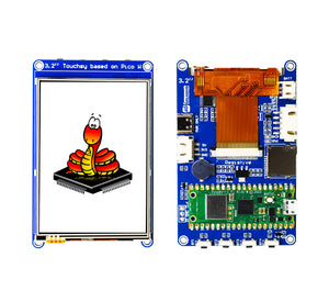
Touchsy - 3.2" Touch LCD Display Based on Pico W
-
Rotary Encoder - LED Array & Touch LCD Powered by Pico W


This is open source product. Kindly check LICENSE.md file for more information.
Please contact support@sb-components.co.uk for technical support.