
MakerPad Pro is an ESP32-powered SmartScreen Hub with a 3.5-inch touchscreen display offering vivid visuals and a 2 MP camera for image related applications. Ideal for IoT projects and creative DIY electronics.
This GitHub provides getting started guides for Makerpad Pro.
- ESP32-WROVER-B module which generic Wi-Fi + Bluetooth® + Bluetooth LE MCU modules that target a wide variety of applications
- Camera for photography related applications
- Capacitive Touch Display 3.5” for user interaction
- Onboard micro SD card storage support for Data logging
- Buzzer for adding audio alert for project
- Type C interface for programming/power
- GPIO pins breakout for interfacing additional peripherals if camera not used
- Boot and Reset Button
- Open source LVGL is supported for designing rich GUI for embedded applications.
- ESP32-WROVER-B contains low-power Xtensa® 32-bit LX6 microprocessors, 448 KB of ROM and 520 KB of on-chip SRAM, with 8MB flash and 8MB PSRAM
- WiFi protocols 802.11 b/g/n and Bluetooth v4.2 BR/EDR and Bluetooth LE
- OV2640 camera built-in having 2M pixel with lens 1/4"
- Camera Pixel Size 2.2 µm x 2.2 µm
- Camera Supports image sizes: UXGA, SXGA, SVGA, and any size scaling down from SXGA to 40x30
- Display Resolution is 320x480 pixel
- TFT LCD driver is ILI9488
- FT6236 Series capacitive touch panel controller IC
- Board Supply voltage 5V
- Operating voltage of GPIO pins 3.3V
- Operating Temperature: -30°C to 70°C
- Stable Image : 0°C to 50°C

- (1) Camera
- (2) 3.5” Touch Display
- (3) Reset Button
- (4) Boot Button
- (5) Power Status LED
- (6) Type C
- (7) TF card slot
- (8) GPIOs breakout*
- (9) Buzzer
- (10) ESP32-WROVER-B module
*Note: Use only camera or breakout GPIOs pin at a time.
-
Camera (OV2640) interfacing with ESP32
ESP32 Camera Function IO5 D0/Y2 Data Pin, for transferring image data from the camera to the ESP32 IO18 D1/Y3 Data Pin IO19 D2/Y4 Data Pin IO21 D3/Y5 Data Pin IO36 D4/Y6 Data Pin IO39 D5/Y7 Data Pin IO34 D6/Y8 Data Pin IO35 D7/Y9 Data Pin IO32 XCLK External Clock, for synchronizing data transfer IO22 PCLK Pixel Clock, signals the start of each pixel's data IO25 VSYNC Vertical Synchronization, marks the beginning of a new frame or image IO23 HREF Horizontal Reference, indicates the start of a new line or row of pixels IO26 SSCB_SDA Serial Data line for I2C bus communication, for camera configuration and control IO27 SSCB_SCL Serial Clock line for I2C bus communication - PWDN Power-Down Pin - RESET Reset pin, connected to ESP reset pin -
SDcard interfacing with ESP32
ESP32 Display Function IO14 CLK SPI Clock pin for SDcard IO13 MOSI MOSI (Master OUT Slave IN) pin of SPI interface for SDcard IO12 MISO MISO (Master IN Slave OUT) pin of SPI interface for SDcard IO4 CS SPI Chip Select pin for SDcard -
Display (ILI9488) interfacing with ESP32
ESP32 Display Function IO14 CLK SPI Clock pin for Display IO13 MOSI MOSI (Master OUT Slave IN) pin of SPI interface for Display IO12 MISO MISO (Master IN Slave OUT) pin of SPI interface for Display IO15 CS SPI Chip Select pin for Display IO26 RST Display Reset pin IO33 D/C Data/Command pin of Display - BL Direct supply to Backlight of display -
ESP32 and Touch (FT6236) controller interfacing
ESP32 FT6236 Touch Function IO26 SDA Serial Data pin of I2C communication IO27 SCL Serial Clock of I2C communication -
Buttons and Buzzer Interfacing with ESP32
ESP32 Hardware Function IO2 Buzzer HIGH - Turn ON, LOW - Turn OFF IO0 BOOT Boot button -
GPIOs Breakout Pins


Breakout Pins Function 3V3 3.3V Positive Supply GND Ground Supply Pin 5V 5V Positive Supply IO5 GPIO5, VSPICS0, HS1_DATA6, EMAC_RX_CLK IO18 GPIO18, VSPICLK, HS1_DATA7 IO19 GPIO19, VSPIQ, U0CTS, EMAC_TXD0 IO21 GPIO21, VSPIHD, EMAC_TX_EN IO23 GPIO23, VSPID, HS1_STROBE IO22 GPIO22, VSPIWP, U0RTS, EMAC_TXD1 IO34 GPIO34, ADC1_CH6, RTC_GPIO4 NOTE: GPIO breakout pins are shared with the Camera, so only use one at a time.


-
Download Arduino IDE from official site and install into your system. We have use Arduino IDE 1.8.19
-
Once installation done will add ESP32 board support into IDE, for this first you need to add below link into preference:
https://raw.githubusercontent.com/espressif/arduino-esp32/gh-pages/package_esp32_index.jsonSelect File > Preference, and add link as show in below image,

-
Now will install ESP32 based different boards as shown in below image, you may get new version option but select 1.0.5 version which is compatible for Makerpad Pro

-
Once done, keeping default settings select the ESP32 WROVER Module with suitable com port (may be different in your case) as shown below,


-
Download library zip file provided here in github.
-
Extract and copy files inside Document > Arduino > Libraries folder. Make sure to restart Arduino IDE whenever you update or add any libraries.

-
Above library folder contains two files TFT_eSPI and FT6236 with pre-configured settings for Makerpad Pro
-
Along with this you will also have to install LovyanGFX Library version 0.3.8 into arduino, steps shown in below image:

-
Make sure you have install above mentioned all libraries for successful compilation of demo examples code provided in GitHub for Makerpad Pro.


-
At this step you are all set to test codes, for easy getting started we have provided various demo example codes in github which you can download and try.
-
Open one example code in Arduino and make sure you have selected correct board with suitable com port, click on upload button to transfer code on ESP32 of Makerpad Pro. Make sure to press Boot button to begin upload process (in terminal you see message -> Connecting....____ ) as shown in below image.

-
Checkout other examples below and build your own custom program codes using those references.

- Example 1 : Simple Buzzer test code
- Example 2 : Display Object demo code working with TFT_eSPI graphics library.
- Example 3 : Click Photos Demo code to test camera, touch and SD card combine.
- Example 4 : Try out Simple Paint App on Makerpad Pro
- and Many more...
Now you are ready to try out your own codes, Happy Coding!
Follow below provided step by step guide to configure, develop and use LVGL UI on Makerpad Pro. To follow along instructions you can download and install Squareline Studio App.

- Schematic
- Hardware Files
- 3D Case File
- PCB 3D Step File
- Getting Started with ESP32 in Arduino
- ILI9488_display_driver Datasheet
- OV2640 Camera Datasheet
- ESP32-WROVER-B Datasheet
- Arduino IDE 1 overview
-
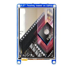
Touchsy - 3.2" Touch LCD Display Based on ESP32 MCU
-
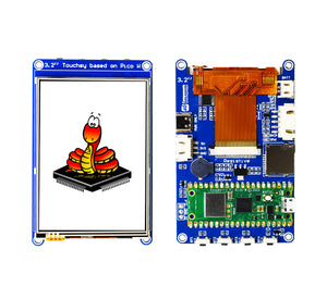
Touchsy - 3.2" Touch LCD Display Based on Pico W
-
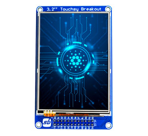
Touchsy - 3.2" Touch LCD Display Breakout Board
-
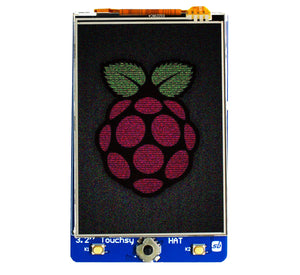
Touchsy - 3.2" Touch LCD Display for Raspberry Pi
This is open source product. Kindly check LICENSE.md file for more information.
Please contact support@sb-components.co.uk for technical support.