Given a D-H representation of a kinematic chain robot, the program generates a crease pattern that folds into a kinematically equivalent robot with compliant joints. The program takes in the D-H representation and assigns the corresponding joint to a location that is sufficiently far from other joints while keeping the same kinematic properties. Then an origami link inspired by the Dubin's path method is created to connect every two conseccutive joints.
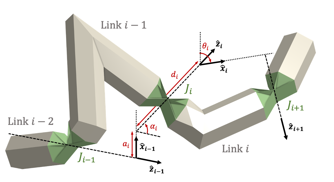
To construct the D-H representation, follow the variable definitaion and numbering system of this kinematic chain mechanism schematic drawing to form a table:
The folded state of the origami module, its spacial operator representation, and its crease pattern is shown here: (A) the origami prism tube, (B) the flange, (C) the elbow fitting, (D) the twist fitting, (E) the revolute joint, and (F) the prismatic joint.

Run scripts Kinegami_******.m and change parameters if desired. For more comprehensive understanding, reference supporting functions.
The crease pattern generated by the algorithm can be output as a .dwg file, its unit is meters. The blue lines indicates the mountain folds, the red indicates the valley folds, and the black lines indicates the boarder edges. We then cut our specimen with the "..." laser cutting machine. For the blue and red line, we perforated the paper by setting the machine parameters to be (power 10, speed 20, ppi 25). For the black line, we cut the paper by setting the machine parameters to be (power 10, speed 20, ppi 750).
7/5/2021: Edited JointAssignment.m to include correct value of rs for Prismatic Joints. Edited Kinegami.m to support plotting for Proximal and Distal Frames. Added new function frameplot.m for frame plotting. Changed manner in which figures are closed in papercut files.
Run any files with Kinegami (preferably Universal and Spherical) Fixing solvedubins3d.m, specifically looking at lines 40-53 (theta calculations)