Lab7_20151125
#Lab 7 - Reflection and clipping
In this lab, we will study how to use the frame buffer we introduced in lab 5 to make the reflection effect, such as a mirror. When applying this effect to render a scene, it is important to make sure that a mirror don't reflect anything behind its surface. To ask openGL don't rendering a certain part of the scene, we use the method called clipping plane.
*This programming practice should be filled in project "mirror".
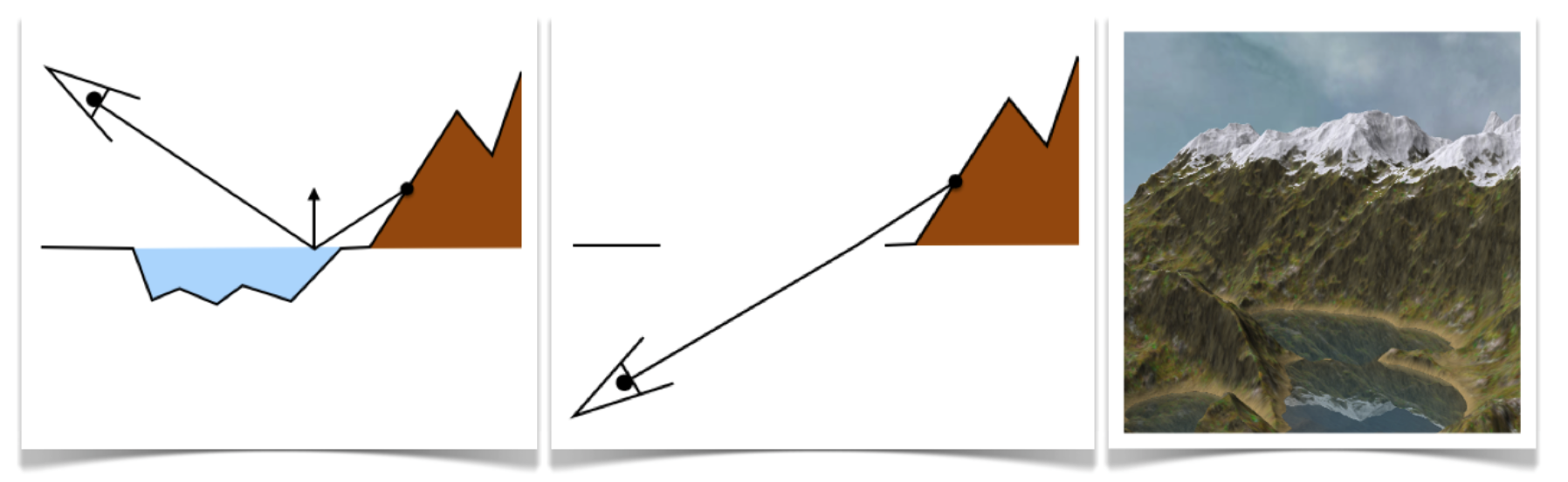
From simple geometrical optics, we know that the image of a reflected image in a mirror is equal to an image seen by a person behind the mirror, standing at a symmetrical position, but substituting the mirror with a piece of transparent glass. That is, the image formed by a perfect mirror is equal to an image formed from a virtual viewing point that is the reflection of the real viewing point. Therefore, when rendering a planar reflection effect, we do not reflect the image of the scene but "reflect" the real viewing point. We implement this method in three steps:
- First, we calculate the symmetrical virtual camera point to the other side of the reflective surface. In our example, the reflective surface lays at the z = 0 plane. Therefore, the virtual viewing point has the same x and y coordinate as the real viewing point, but has its z coordinate negated.
- Secondly, we render the scene from this virtual viewing point to a frame buffer object. Note that we should render everything in the scene but not the reflective surface itself, as you never see a mirror within its own reflection.
- In the last step, we use the frame buffer object as the texture for the reflective surface. We use the pixel coordinate on the screen to sample into this texture, instead of using the UV coordinate that comes with the reflective object. This is an important technique to remember in order to make the result reflection rendered in correct perspective.
The first two steps are done in the display() method in main.cpp:
    // TODO: 1. mirror the camera position about the Z=0 plane
    // 2. create new VP for mirrored camera
    // 3. render the object using the mirrored camera, but not the floor
    // it should be rendered to the framebuffer object (remember bind/unbind)

    vec3 cam_pos_mirror = cam_pos;
    cam_pos_mirror(2) = -cam_pos(2);
    mat4 view_mirror = Eigen::lookAt(cam_pos_mirror, cam_look, cam_up);
    fb.bind();
        glClear(GL_COLOR_BUFFER_BIT | GL_DEPTH_BUFFER_BIT);
        mesh.draw(model, view_mirror, projection);
    fb.unbind();
The shinyfloor object now has two textures to shade its surface: the original "wooden texture", and a texture image that resembles the reflected image of the scene. In the fragment shader of the _floor class, we blend these two textures together to render the floor as reflective. The following code segment should be filled in mirror_floor\Floor_fshader.glsl:
void main() {
/// TODO: 1. Query window_width/height using the textureSize function on tex_mirror
/// Use gl_FragCoord to build a new [_u,_v] coordinate to query the framebuffer
/// This will give you the screen pixel coordinate of current fragment.
/// NOTE: Make sure you normalize gl_FragCoord by window_width/height
/// You will have to flip the "v" coordinate as framebuffer is upside/down
/// TODO: 2. Mix the texture(tex,uv).rgb with the value you fetch by
/// texture(tex_mirror,vec2(_u,_v)).rgb
float window_width = textureSize(tex_mirror, 0).x;
float window_height = textureSize(tex_mirror, 0).y;
float ScreenU = gl_FragCoord.x/window_width;
float ScreenV = 1 - gl_FragCoord.y/window_height;
vec3 color_from_texture = texture(tex,uv).rgb;
vec3 color_from_mirror = texture(tex_mirror,vec2(ScreenU,ScreenV)).rgb;
color = mix(color_from_texture, color_from_mirror, vec3(.15));
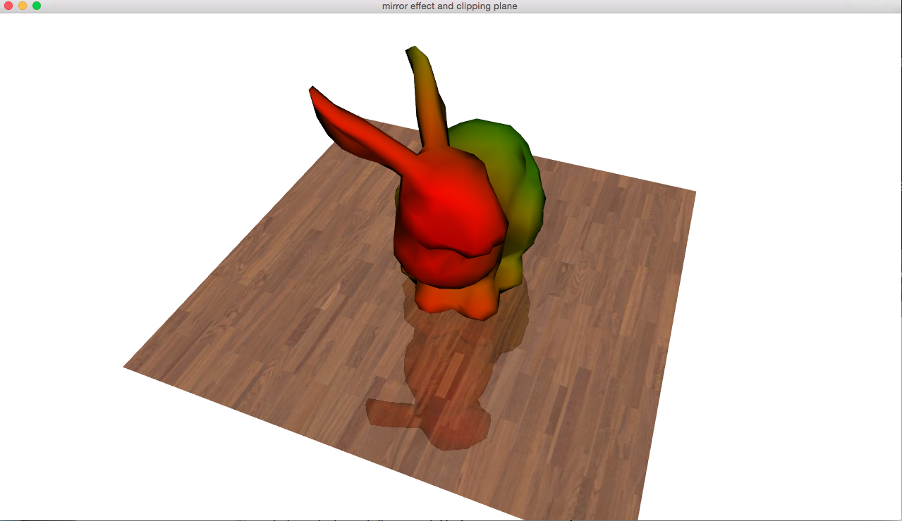
}At this point if you run the program, you should see a bunny with a shiny, reflective wooden floor.
The clipping plane is used to instruct the openGL system only drawing part of the geometry in the scene. Historically, it used to be a real plane that cut through the scene, and only geometry on one side of the plane will be drawn on screen. In modern GLSL, the clipping plane is generalized to be just an interpolative per-vertex property. As put by the openGL 4 documentation:
The gl_ClipDistance variable provides a forward compatible mechanism for controlling user clipping. The element gl_ClipDistance[i] specifies a clip distance for each user clip plane i. A distance of 0.0 means that the vertex is on the plane, a positive distance means that the vertex is insider the clip plane, and a negative distance means that the point is outside the clip plane. The clip distances will be linearly interpolated across the primitive and the portion of the primitive with interpolated distances less than 0.0 will be clipped.
[https://www.opengl.org/sdk/docs/man/html/gl_ClipDistance.xhtml]
This means you can simply set a "clipping number" on every mesh vertex in anyway you want, just like depth or colour, and pixels will be drawn if the interpolated "clipping number" is greater or equal than zero, or discarded if the "clipping number" is less than zero.
But it is still helpful to calculate the "clipping number" in a geometrically meaningful way. For a clipping plane that is defined as a normal vector N and a point P, we can use the dot product to determine on which side of the plane lays another given point Q. We simply calculate Q·N - P·N and use the result as the "clipping number"; if the result is greater than zero, we say its on the positive half of this clipping plane, otherwise it's on the negative half.
To use the clipping plane functionality of openGL, we need to enable it first. Let's modify the Mesh class to enable this. Go to the Mesh.h file in mirror_mesh\Mesh.h, and adds glEnable(GL_CLIP_PLANE0) and glDisable(GL_CLIP_PLANE0) in the draw method, just before and after the glDrawElements() command.
 glEnable(GL_CLIP_PLANE0);
 glDrawElements(GL_TRIANGLES,
                /*#vertices*/ 3*mesh.n_faces(),
                GL_UNSIGNED_INT,
                ZERO_BUFFER_OFFSET);
 glDisable(GL_CLIP_PLANE0);
Then, we need to add a line into the vertex shader of the mesh class to set the clipping value. In GLSL, the clipping plane information is automatically maintained in the gl_ClipDistance[] array that is implicitly declared. In this example, we will set the clipping plane to be the y = 0 plane and pointing to the positive Y direction. That is, the plane is defined by a point P=(0,0,0) and N=(0,1,0). Since P·N = 0, we shall put the (negated) result of Q·N into gl_ClipDistance[0].
Please keep in mind that Q must be in the world space, not screen space. Thus, we should take the coordinate of the vertex after we applied the world transform, but before the view and perspective transform.
At the end of the main() method in mirror_mesh\Mesh_vshader.glsl, add the following line:
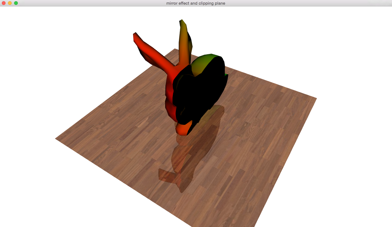
gl_ClipDistance[0] = .1+dot(vec3(world), vec3(0,-1,0));This will cut our bunny in half about the Y axis.
-
If the reflective plane doesn't align with one of the xyz axes, then the symmetrical virtual camera point must be calculated instead of just negate the z-coordinate. What is the method of calculating such a symmetrical point of a given camera point V with an arbitrary given plane defined as a normal N and a point on the plane P?
-
When creating a reflective water surface, for example a lake, not every part of your terrain model should be reflected by the lake surface. Which part is reflected and which is not?