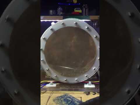
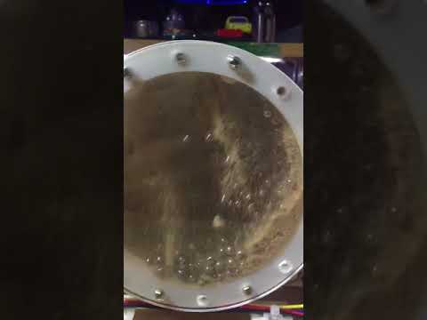
This ball mill was made for grinding sand and cleaning objects like rusty bolts. It works but takes a very long time to grind sand down, this is because of the size of the balls are too small. Getting larger balls will help. Some professionals that design and manufacture mill for industry helped in the design of the lifter and the correct speed for milling. The professionals were interested in how long it would take for the lining of the mill to be worn out. This is yet to be tested.
https://tinkersprojects.com/project/3d-printed-ball-mill/
The parts can be found here: https://www.thingiverse.com/thing:2713357


The program is currently has been thrown together and will need to be redone at somepoint. The Program dose work it just need to be cleaned up. Contact me if you want to help.
After powering the mill with 12V DC power, settings can be seen/changed using the LCD and can be altered using the 3 buttons (up, down and enter). Speed and duration are the 2 settings that can be set to control the mill. While the mill is in operation, the LCD will display the current speed and the time left of milling. By pressing the enter button, the mill will stop. Click below to watch the video.
- 1 x controller, PLEX or Arduino UNO (see below for more details)
- 1 x photo interupt
- 2 x 20mm M3 srew
- 2 x 20mm M3 srew
- 1 x 100mm M8 bolt
- 2 x 60mm M8 bolt
- 4 x M8 nut
- 4 x 608 bearing
- 1 x 12V 688RPM 9Kg.cm geared DC motor, part no.:JGB37-550
- 4 x rubber feet
- 100 x 6mm-10mm ball bearings
The controller used is the PLEX board from plexcontroller.com (an Arduino UNO can be used instead). The controller Uses a 16x2 LCD and buttons inputs to set settings display speed/timer while in operation. A photo interrupt and encoder are used to calculate the speed of the mill to be compared to the set speed. This comparison is analyzed and an output is used to control a MOSFET for the motor.
A diode and capacitor were used to block current drawn from the controller to the DC motor. If not used the controller will rest.