Complete Mesh for a damper in a duct (starting from an STL geometry)
This tutorial will demonstrate how to read a STL geometry and create a volume mesh for a CFD simulation using enGrid. The geometry, which will be used for this tutorial, represents an adjustable damper within a duct. The file containing the geometry is called Damper.stl and can be found in the /tutorials/01_Damper folder.
To start, please open enGrid (./run.bash) and import the file choosing:
- Import » STL
The orientation of the 3d view can be modified using the mouse:
- Left mouse button (LMB) and Ctrl-LMB - rotates
- Middle mouse button (MMB) - moves
- Mouse scroll wheel - zooms
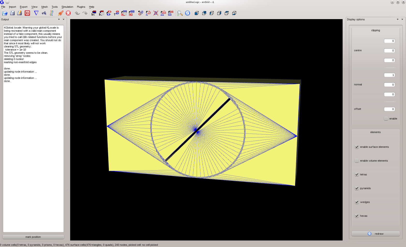
|
| Figure 1: After importing the surface mesh |
To check the integrity of the imported surface, choose:
- Tools » Check surface integrity
enGrid colours the single faces of the surface grid in order to determine which side of the surface is inside a flow domain and which is outside. To do so a pale green and a pale yellow is used. It's recommended to ensure the outside is coloured in green (although it doesn't matter which colour has been selected as long as all outer faces are in one colour and all inner faces are in the other colour).
Figure 1 shows pale yellow therefore change the orientation by choosing
- Mesh » change surface orientation
- File » Save Grid As
Unfortunately all faces belong to the same boundary condition and thus it is not possible to see inside the domain. To change this you can pick a surface of the geometry and then change its boundary condition to a different value. To pick the face of the symmetry plane in the front, please point the mouse over a triangle of the symmetry plane and press the P key on your keyboard. Afterwards you should see something similar to Figure 2.

|
| Figure 2: Picking a boundary face |
To change the boundary code, please select:
- Mesh » set boundary code (S)

|
| Figure 3: Hiding the front |
Now, do the same with the following faces of the duct:
- back (boundary condition 2)
- top (boundary condition 3)
- bottom (boundary condition 4)
- left (boundary condition 5)
- right (boundary condition 6)
- top (boundary condition 7)
- bottom (boundary condition 8)
- left side (boundary condition 9)
- right side (boundary condition 10)
- back side boundary condition 11)
Choose:
- Simulation » Edit boundary conditions (E)
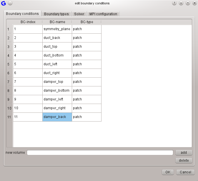
|
| Figure 4: Renaming the boundary conditions |
Selecting:
- View » Boundary codes (V)
Now would be a good time to save your work as Damper_S1.egc.
Although the imported geometry has a surface mesh, this mesh needs to be improved. Therefore, choose
- Mesh » edit surface parameters
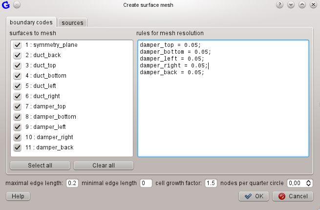
|
Figure 5: Create Surface Mesh - You can copy from the code below:
damper_top = 0.05; damper_bottom = 0.05; damper_left = 0.05; damper_right = 0.05; damper_back = 0.05; |
Note: The rules for the mesh resolution will be combined automatically by enGrid meaning they may look different when re-opening the view.
Now select
- Mesh » create/improve surface mesh
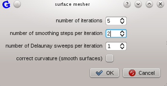
|
| Figure 6: Surface Mesher |
The meshing process will start after clicking on OK. You can watch the progress in the output window. Note the message on the bottom of enGrid's main window telling you the application is working. When the calculation has finished, click into the 3D view to update it. You can use the V-key to open the select boundary codes dialogue and select what is shown (e.g. deselect the symmetry-plane to look inside the geometry).
Start the surface meshing process several times (Mesh » create/improve surface mesh) to improve the mesh using the settings as above. Watch the fluctuation ratio and change ratio dropping in the Output window. A negative change ratio can often be used as an indicator for the quality of the mesh, but you need to verify it visually. You should see something like Figure 7 after executing the process three times.
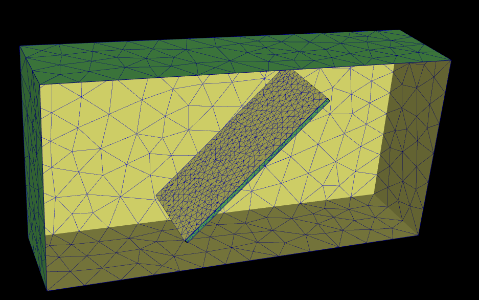
|
| Figure 7: Improved Surface Mesh |
The mesh of the damper edges needs to be improved. Choose
- Mesh » edit surface parameters
damper_top <AND> damper_left = 0.01;
damper_top <AND> damper_right = 0.01;
damper_top <AND> damper_back = 0.01;
damper_bottom <AND> damper_left = 0.01;
damper_bottom <AND> damper_right = 0.01;
damper_bottom <AND> damper_back = 0.01;
Figure 8 shows the resulting rules.
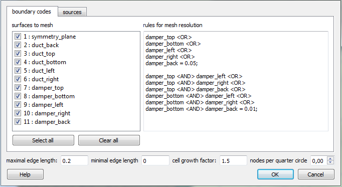
|
| Figure 8: Settings To Improve Damper Edges |
Select
- Mesh » create/improve surface mesh
Note: You can avoid changing these values for every step by adjusting the default values. The relating dialogue can be found on the surface meshing tab in
- Tools » Configure enGrid.
Deselect displaying the duct's walls by pressing the V-key and the duct's boundary codes. Rotate the damper to ensure the meshing of the edges corresponds to your needs.
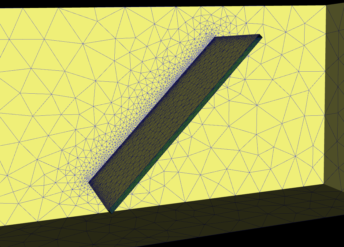
Figure 9 shows the resulting mesh:

|
| Figure 9: Improved Meshing of the Damper Edges |
Choose
- Mesh » edit surface parameters

|
| Figure 10: Adding a Cone |
Click OK two times and select
- Mesh » create/improve surface mesh
|
| Figure 11: Improved Mesh in the border zone of the damper/duct |
Note: You might need to ensure the duct's faces are displayed by selecting them (V-key).
Ensure to save your work as Damper_S3.egc.
A volume can be defined by adding a new volume, indicating which boundary codes are part of it and which colour the outer side of the boundary relative to the volume currently has. To do this, select:
- Simulation » Edit boundary conditions
- Add a new volume by entering a name like vol in the new volume field and clicking on add.
- In the new column vol, set all cells to green by double-clicking on them, select green from the drop-down box and then click OK.
Creating a first volume mesh, including the boundary layer, is fairly easy now. To create the grid, simply select:
- Mesh » create prismatic boundary layer
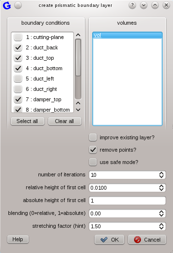
|
| Figure 12: Create prismatic boundary later |
Click OK to start the meshing process. You can watch the progress in the output window on the left side of the screen. Again enGrid indicates that it is busy in the status line at the bottom of the window.
You can display the volume mesh as soon as enGrid has finished the computation. You'll find an area labelled elements on the right hand of enGrid's main window. Select enable volume elements, deselect enable surface elements, then click on redraw. You'll realize that only the boundary layer has been filled with a volume mesh. Please choose
- Mesh » create/improve volume mesh (NETGEN)
The resulting volume mesh should look like Figure 13.
|
| Figure 13: Volume mesh |
The volume mesh within the boundary layer needs to be refined to allow good simulation results. This can be done by dividing the prism layer into several layers. Choose
- Mesh » divide prismatic boundary layer
DO NOT FORGET: you can only divide the boundary layer if you already have both the initial boundary layer and volume mesh, as shown in the previous section!
See Figure 14 showing the improved volume mesh.

|
| Figure 14: Improved boundary volume mesh |
EnGrid allows to extrude a volume mesh. Do do so, choose
- Mesh » extrusion
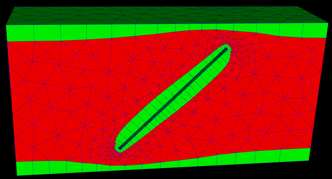
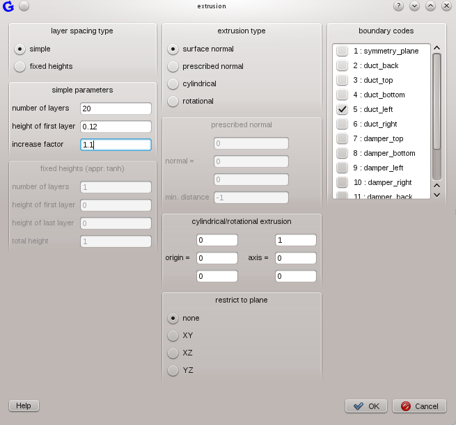
Use the settings as given in Figure 15 to extrude the volume mesh in input direction of the duct and the settings as given in Figure 16 to extrude the volume mesh in output direction of the duct.
|
| Figure 15: Settings for Extrusion of the volume mesh (left) |

|
| Figure 16: Settings for Extrusion of the volume mesh (right) |
Note: The left side has been extruded using an increasing cell height (increase factor = 1.1) whereas a fixed cell height has been used for the right side (increase factor = 1).
Figure 17 shows the resulting mesh.

|
| Figure 17: Extruded volume mesh |
Finally, after finishing the mesh, enGrid allows to export it to OpenFOAM. This can be done by selecting
- Export » OpenFOAM » OpenFOAM (grid only).
- Export » OpenFOAM » OpenFOAM (grid+solver parameters)
...
...
...