Drawing Bounding Boxes with a Web Component
In this tutorial we'll use the Web Component support added in XML3D 5.2 to create our own HTML element that draws the bounding box of a given XML3D element. To do this we'll:
- Create the HTML template for our element
- Add Javascript logic to our element to make it interactive
- Register our new web component with XML3D
- Add an instance of it to an XML3D scene and use it to draw bounding boxes
Before we begin you may want to familiarize yourself with Web Components and how they work. Also, some browsers don't support web components yet so you may need to use a polyfill alongside xml3d.js to provide the missing functionality!
Note: This tutorial more or less replicates the component used in the XML3D Bounding Box example, so check that out for an idea of where we're going with this tutorial.
The first step in creating a web component is to craft an HTML <template>. The body of this template is what will be created inside the Shadow DOM of every instance of our custom element. In our case we'll need some XML3D elements in here that turn the bounding box of an object into an actual box of lines to be drawn by XML3D. Lets start with the template element itself:
<template name="xml3d-boundingbox" target="">

</template>
Every template element needs to specify a name. This will be the tag name of our custom element and must contain a hyphen (-). We also add a 'target' attribute that we'll use as one way to tell our element which XML3D object we want to see the bounding box of.
Now lets add the XML3D elements to draw the bounding box:
<template name="xml3d-boundingbox" target="">
   <material id="bboxMaterial" model="urn:xml3d:material:flat">
      <float3 name="diffuseColor">1 0 0</float3>
   </material>

   <mesh type="linestrips" material="#bboxMaterial">
      <data compute="position, vertexCount = xflow.genLinesFromBBox(bbox)">
         <float3 name="bbox">0 0 0 0 0 0</float3>
      </data>
   </mesh>
</template>
Our <material> definition is pretty ordinary, the interesting stuff starts inside our <mesh> object. First, we set the type of the mesh to linestrips. In this mode XML3D will work its way through the list of 'vertexCounts' that we supply the mesh, taking 'vertexCount' vertices at a time and drawing a line between them. For example, a vertexCount of 3 would draw a line between the next 3 sets of positions, each of which represents one vertex.
In XML3D bounding boxes are axis aligned and only have two 'points', the minimum and the maximum point, as shown below:
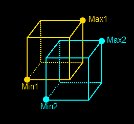
Obviously this is not the list of positions that the <mesh> is expecting, so we'll need to generate that list out of the information we do have: the two points. We can do this using a custom Xflow operator that takes the two points as input and generates the outputs position and vertexCount, which together define the linestrips that the <mesh> needs to draw the box. Writing this operator is beyond the scope of this tutorial, but you can see the source code in the Bounding Box example that this tutorial replicates.
That about does it for our template, but we're going to need some way to put the right input data into that Xflow operator (the float3 element with name bbox), because right now all it's going to do is draw a box with zero size! Remember, everything inside our template will be inside the Shadow DOM of our custom element, inaccessible from the outside. So how can we do this?
Our web component is going to need a second... component, namely some Javascript to make it interactive and to put the right bounding box data into the input of our Xflow operator. Lets create a new Javascript file and start defining the prototype for our custom element, which will let us add our own functions to it and tap into the built in lifecycle callbacks that web components provide.
The first thing we'll need to do is react to changes in the target attribute. Lets decide that this attribute accepts a string as input that corresponds to the HTML ID of the element we want to draw the bounding box of. When we want to draw the bounding box of a different element, we just change the target attribute of our xml3d-boundingbox element to that other element's ID.
var ourPrototype = {
   attributeChangedCallback: function(attr, oldVal, newVal) {
      if (attr === "target") {
         var otherElement = document.getElementById(newVal);
         if (!otherElement) {
            return;
         }
         var bbox = otherElement.getWorldBoundingBox();
         this.shadowRoot.querySelector("float3[name='bbox']").textContent = bbox.toDOMString();
      }
   }
};
The attributeChangedCallback is one of the lifecycle callbacks that all custom elements can tap into. Any time an attribute on our element changes this function will be called. If that attribute is target we first find the element in the document with the given ID. If we find one we then get its world space bounding box through the getWorldBoundingBox function that XML3D provides on all scene elements.
Once we have the bounding box we need to feed it into our Xflow operator so we can generate linestrips out of it. Remember, everything that was in our <template> is now inside the Shadow DOM of our custom element, so this is where we need to look to find the float3 element that feeds the operator. We use a query selector that reads "find the first float3 element with a 'name' attribute that has the value 'bbox'" to find that float3 element. Lastly, we convert the bounding box to a DOM string and insert it into the text content of the float3 element. From here Xflow will automatically re-compute the operator and generate our lines for us.
Whew. So this is ok, but maybe not every element that we're interested in has an ID. Lets add another function to our bounding box element that we can call through Javascript, taking directly as input the HTML element that we want to see the bounding box of:
var ourPrototype = {
   attributeChangedCallback: function(attr, oldVal, newVal) {
      if (attr === "target") {
         var otherElement = document.getElementById(newVal);
         if (!otherElement) {
            return;
         }
         this.showBBoxFor(otherElement);
      }
   },

   showBBoxFor: function(element) {
      var bbox = element.getWorldBoundingBox();
      this.shadowRoot.querySelector("float3[name='bbox']").textContent = bbox.toDOMString();
   }
};
That looks like enough to do what we need, there's only one more step before we can start using our web component: registering it with XML3D.
Before a web component can be used it has to be registered with XML3D (and with the browser itself, but XML3D takes care of that part for us). We can do this directly in the Javascript file of our component, that way it will be registered automatically whenever we include it in a scene (after the xml3d.js script!)
var ourPrototype = {
   attributeChangedCallback: function(attr, oldVal, newVal) {
      if (attr === "target") {
         var otherElement = document.getElementById(newVal);
         if (!otherElement) {
            return;
         }
         this.showBBoxFor(otherElement);
      }
   },

   showBBoxFor: function(element) {
      var bbox = element.getWorldBoundingBox();
      this.shadowRoot.querySelector("float3[name='bbox']").textContent = bbox.toDOMString();
   }
};

window.componentReady = XML3D.registerComponent("bbox-template.html", {proto: ourPrototype});
That's really all there is to it. XML3D will load the HTML file containing our element's <template> and then register it with the browser. Giving your own prototype for the element is optional, but since we do XML3D will pass that along to the browser as well.
Since this whole process may take a while the registerComponent function returns a Promise that resolves once the web component is ready to be used. It's best to make use of this to wait until all web components are ready to go before creating instances of them in your scene. In this case we're just going to export the Promise to window so we can use it later, but in serious use cases you'll probably want to create your own system of registering components and waiting for them to finish loading.
Finally all that preparation is done and we're ready to create our very own <xml3d-boundingbox> element in an XML3D scene. Lets take a look at the relevant parts in the Bounding Box example:
<head>
...
   <!-- The Javascript files used to define our bounding box web component -->
   <script type="text/javascript" src="genLinesFromBBox.js"></script>
   <script type="text/javascript" src="boundingbox-component.js"></script>
...
</head>
We've included the custom Xflow operator and the boundingbox-component.js file that we created earlier with our custom element prototype. This loads and registers the component with XML3D. We then wait on the Promise that we exported to window earlier which resolves when the component is ready to be used:
window.componentReady.then(function() {
   // Create an instance of the <xml3d-boundingbox> element
   var bboxElement = document.createElement("xml3d-boundingbox");
   document.querySelector("xml3d").appendChild(bboxElement);

   // Add a click listener to the group surrounding the teapots
   document.querySelector("#teapotGroup").addEventListener("click", function(evt) {
      // Set the target of the boundingbox web component to the clicked teapot
      document.querySelector("xml3d-boundingbox").showBBoxFor(evt.target);
   });
});
Once the Promise resolves we create an instance of our component using the standard document.createElement function and append it to the <xml3d> element. Then we use the showBBoxFor function on our element to show the bounding box of a teapot mesh whenever one is clicked.
You can find the full source code to the final scene in our examples GitHub repository.
In the example you might have noticed the template for the bounding box element has one more attribute: color. XML3D provides a built-in way of linking attributes to Xflow inputs. What that means is you can define an attribute on your template, then use the value of that attribute inside any Xflow value element (like <float3>) using handlebar notation:
<template name="xml3d-boundingbox" target="" color="0.2 0.5 1.0">
    <material id="bboxMaterial" model="urn:xml3d:material:flat">
        <float3 name="diffuseColor">{{color}}</float3>
    </material>
    ...
</template>
Any time the attribute changes XML3D automatically carries that change over into the Xflow element for you. In this case the color of the bounding box can be changed simply by changing the color attribute of any instance:
<!-- Make the bounding box red -->
<xml3d-boundingbox color="1 0 0"></xml3d-boundingbox>
Note that the value in the attribute is carried over as-is, so it needs to be in the right format to be used in Xflow (generally that means space separated and with the correct number of values).