I've been working on various PCB projects including Raspberry Pi Zero stuff. I'm a super newbie in terms of electronic circuit and PCB design, but I've placed them here in this repo just in case someone finds them useful.
By uploading *.kicad_pcb file to OSH Park, anyone can get the exact same PCB. Add-on boards for Raspberry Pi Zero would cost $15/3 boards or so, and ones for Raspberry Pi would cost $29/3 boards or so.
いろいろと作っていますが、 Raspberry Pi Zero 関連が多いです。電子回路 もPCB設計も超ど素人ですが、何かの参考になれば。
はんだ付け初心者のためスルーホール/DIPが基本になっていますが I2Sになる とそうも言ってられず表面実装はじめました。
OSH Park に *.kicad_pcbファイルをアップロードすれば、誰 でも下記のPCB基板を手に入れることができます。Raspberry Pi Zero 用で $15/3枚、Raspberry Pi用で$29/3枚ほどです。
This is designed for a sensor light based on ESP32 (Lolin32), a cheap doppler radar RCWL-0516 and WS2812B (NeoPixel) strip.
ESP32ベースのセンサーライトのためのPCBです。安価なドップラーレーダー RCWL-0516 をセンサーに使い、WS2812B (NeoPixel)をライトに使っています。
- WEMOS Lolin32
- Alibaba Neopixel strip
- Alibaba RCWL-0516
- Anker PowerCore+ Mini
- Capacitor 1000uF
- Resister 470R
- Resister 10KR
- BSS138
- Slide Switch(SPDT)
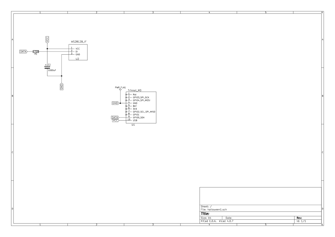
This is desiged for driving Neopixel (WS2812B) strip. This requires a Adafruit Trinket Mini 5V. If you want to drive many WS2812Bs, you might want to use a USB mobile battery like Anker PowerCore+ Mini to attach to the Trinket. This power will go to VCC pin for WS2812B through USB pin on the Trinket. (For example, each WS2812B consumes 60mA at maximum brightness, i.e. 30 of those will consume 1.8A.)
Neopixel (WS2812B) を駆動するためのPCBです。Adafruit Trinket Mini 5V専用となっています。 多数のWS2812Bを駆動するため、Anker PowerCore+ MiniなどのUSBモバイルバッテリーからTrinketに電源を供給することが前提です。この電源はTrinketのUSBピンからパススルーでWS2812B用のVCC端子に供給されます。 (WS2812Bはフル点灯時で60mA消費しますので、30個で1.8Aほど必要になります。)
- Adafruit Trinket Mini 5V
- Alibaba Neopixel strip
- Anker PowerCore+ Mini
- Capacitor 1000uF
- Resister 470R
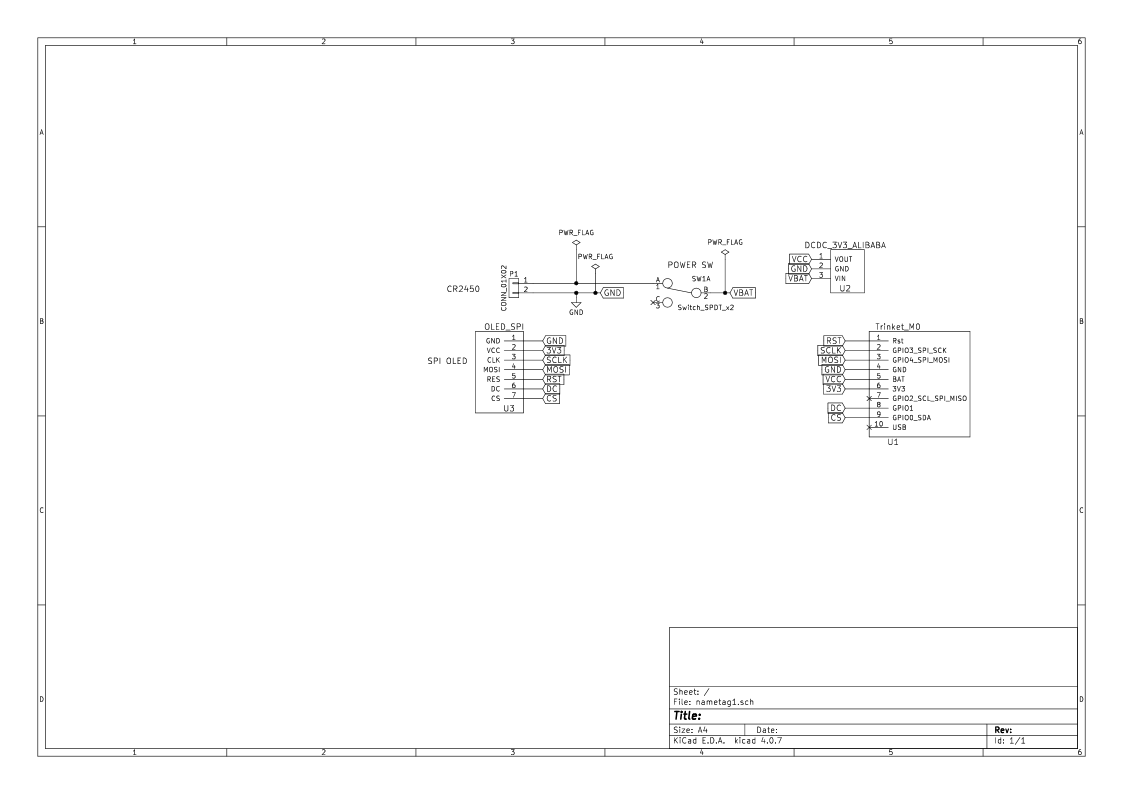
This is designed for the "programmable nametag" project. This PCB is to basically run a Trinket M0 off a single coin cell battery CR2450, which is a very challenging subject. Due to discharging behavior of CR2450, this runs for 30-min only at this point.
プログラマブル名札プロジェクト向けのPCBです。Trinket M0 + OLEDをCR2450で駆動するという難題に挑戦しています。 CR2450の放電特性により現時点では30分の稼働が限界です。
- Adafruit Trinket M0
- Alibaba 0.96" SPI OLED module
- Alibaba 3.3V regulator module
- Slide Switch(SPDT)
- CR2450 Holder
- CR2450
A pHAT-like add-on board that adds a headphone jack to your Raspberry Pi Zero. This PCB uses a PWM audio circuit remixed from PiZero PWM audio by Adafruit that is licensed under CC BY-SA 3.0.
NOTE: Noise is pretty loud, like AM radio.
Raspberry Pi Zero にヘッドフォン端子をつけるための pHAT のようなボード です。
このPCBの回路は PWM オーディオ出力回路 by Adafruit から CC BY-SA 3.0 に 基づいてリミックスされた回路を使用しています。
NOTE: 音声にけっこうノイズが乗ります。AMラジオくらい。
A pHAT-like add-on board that adds a cursor key (via GPIO) and a 0.96" I2C OLED to your Raspberry Pi Zero.
Raspberry Pi Zero にカーソルキーと 0.96" I2C OLED をつけるための pHAT のようなボードです。
A pHAT-like add-on board that adds a game pad (via GPIO) your Raspberry Pi Zero.
Raspberry Pi Zero にゲームパッドをつけるための pHAT のようなボードです。
A pHAT-like add-on board that adds a game pad (via GPIO) that is designed to be used together with Adafruit PiTFT 2.2. Please note that the game pad is laid out up-side-down by design.
UPDATE: Moved GPIO pins to avoid I2S-related pins (12, 35, 40). Moved GND pins to GNDD pins used in zeroamp1 circuit. Changed footprint of momentary switches to Panasonic EVQ11.
Raspberry Pi Zero にゲームパッド(上下さかさま)をつけるための pHAT の ようなボードです。Adafruit PiTFT 2.2 と組み合わせることが前提の 設計ですが、他にも使えるかもしれません。
UPDATE: I2Sで必要なピン(12,35,40)を使わないように修正。また、I2Sボード と共通のGNDD(デジタル用GND)ピンを使うように修正。モメンタリースイッチ のフットプリントを巷によくある6mm角4ピンから Panasonic EVQ11互 換 に変更。
A pHAT-like add-on board that adds a cursor key (via GPIO) and a 1.3" SPI OLED to your Raspberry Pi Zero.
Raspberry Pi Zero にカーソルキーと 1.3" SPI OLED をつけるための pHAT のようなボードです。
UPDATE: I2Sで必要なピン(12,35,40)を使わないように修正。また、I2Sボード と共通のGNDD(デジタル用GND)ピンを使うように修正。
A pHAT-like add-on board that adds a headphone jack, 0.96" I2C OLED, and a 7-button cursor key (via GPIO) to your Raspberry Pi Zero.
This PCB uses a PWM audio circuit remixed from PiZero PWM audio by Adafruit that is licensed under CC BY-SA 3.0.
UPDATE: During something is shown on the OLED, terrible noise appears on the audio output, like an AM radio that is not tuned in.
Raspberry Pi Zero にヘッドフォン端子と、0.96" I2C OLED と、7ボタンのカーソルキーをつけるための pHAT のようなボードです。
このPCBの回路は PWM オーディオ出力回路 by Adafruit から CC BY-SA 3.0 に 基づいてリミックスされた回路を使用しています。
UPDATE: OLEDに何か表示させているとそのノイズがひどいです。チューニングが合っていないAMラジオくらい。
A pHAT-like add-on board that adds I2S DAC PCM5102A that works as an headphone amplifier (HPA) (sort of). As you may know, PCM5102's output pin is only line level, not headphone level. But it just worked when I plugged an earphone/headphone with a breakout board out there. That was the beginning of this project.
Probably thanks to the minimized analog circuitry, noise level is pretty low and sound quality is surprisingly good. (Much better than piamp2 below.)
USE WITH CAUTION as a headphone amplifier. According to PCM5102A data sheet, the output minimum impedance is 1kR and the effective voltage is 2.1V, therefore the maximum effective current is 2.1mA. This circuitry inserts 1kR registers there to limit the current to this maximum value. This is tested with an earphone that came with iPhone and it works fine, but please try at your own risk.
Raspberry Pi Zero に I2S DAC である PCM5102A を搭載して無理やりヘッドフォ ンアンプとして使ってみようという pHAT のようなボードです。PCM5102Aの出 力はラインレベルですが、巷のブレイクアウ ト にイヤフォンやヘッドフォンをつないだら意外に聴けたので。
アナログ回路が最小限のためか、iPhone付属イヤフォンではノイズが感じられ ず、高音質です。(piamp2よりも音がいいです)。
ただし PCM5102Aで直接ヘッドフォンを駆動するのはもともと厳しいため、使用 の際は注意が必要です。データシートによると出力側の最小インピーダンス 1kRと実効電圧2.1V から引き出せる実効電流が最大 2.1mAとなります。この回 路では 1kRの抵抗を入れることによって電流をこの最大値ぎりぎりに制限して います。実験した範囲ではiPhone付属イヤフォンで使えていますが、くれぐれ も自己責任でお願いします。
A HAT-like add-on board that adds I2S DAC PCM5102A, OPAmp NJM5532D and a headphone output jack to Raspberry Pi 3. This should work as an headphone amplifier (HPA) more natually than zeroamp1 thanks to NJM5532D.
This is not a high quality board. Every time Pi tries to show a character over SSH for example, a small noise comes in, meaning there seems (lots of) issues in terms of analog circuit design.
UPDATE: Fixed a bug in potentionmeter pins.
Raspberry Pi3 に I2S DAC である PCM5102A とOPアンプ NJM5532D を搭載して ヘッドフォンアンプとして使ってみようという pHAT のようなボードです。ア ナログ回路的な問題が多々あるようで、Raspberry Piがsshターミナル越しにテ キストを出力した時などにヘッドフォン出力に多少ノイズが入ります。
UPDATE: ポテンションメータのピン接続が間違っていたので直しました。
SMT soldering practice board featuring PCM5102A (TSSOP-20) that happens to be a breakout board as well.
TSSOP-20 パッケージである PCM5102A を使って表面実装のはんだ付けを練習するための基板です。結果的にブレイクアウトとしての機能も兼ねています。
- Electronic circuit / 電子回路全般 : Adafruit
- PCB fabrication service / PCB生産委託 : OSH Park
- CAD software / CAD ソフト : KiCAD
Contents posted in this site is for informational purpose only and nothing is guaranteed. Headphone amplifier is especially dangerous as it can cause permanent damage to your ears. すべて無保証です。特にヘッドフォンアンプ基板は大変危険です。鼓膜を損傷するかもしれません。くれぐれも自己責任でお願いいたします。


