ReferenceRouterWalkthrough
In this section we will go through the available tools to communicate with the Hardware Component of the Reference Router (HardCORR) and go through the process of modifying the design, simulating it, and finally implementing it. The tools that we will go over quickly are a Java GUI and a Standalone Command Line Interface (CLI).
The Java GUI allows the user to change entries in the Routing Table and ARP cache as well as the router's MAC and IP addresses. It also provides updates on counter values and graphs of throughput and much more. The GUI has a part that is written in C that provides the interface between the Java binaries and the driver. This native library is compiled from the nf2util.c file that contains the readReg and writeReg utilities used in the previous section. The library connects to the GUI using the Java Native Access (jna) library.
To build the GUI, first make sure that you have Sun's Java Development Kit (version >=1.6.0) installed and make sure the java, javac, and jar binaries are in your path (otherwise, you can edit the Makefile under lib/java/gui to reflect the actual locations). Then cd into NF2/lib/java/gui and type make clean. Then type make. You should get output similar to below:
make[1]: Entering directory `/home/jnaous/NF2/lib/C/common'
gcc -fpic -c nf2util.c
gcc -shared nf2util.o -o libnf2.so
make[1]: Leaving directory `/home/jnaous/NF2/lib/C/common'
Building java...
Done
Writing router gui manifest...
Building router jar...
Writing script to start router gui...
Writing event capturing router gui manifest...
Building event capturing router jar...
Writing script to start event capturing router gui...
To run the GUI for the router, cd into netfpga/lib/java/gui and type ./router.sh. The GUI should pop-up. The GUI constantly polls the data it reads from the hardware. To make updates faster, you can change the update rate under the File menu at the top left.
The Quickstart Panel provides a summary of things that can be done with the hardware. There is also a tab for viewing statistics and a tab for details. The details page will show the data path pipeline we saw earlier under the Reference NIC Walkthrough with clickable buttons. Clicking on those buttons will open up new buttons with more details and configuration settings.
A standalone small CLI that allows you to change routing table entries, ARP cache entries, and other settings is also provided in case the user doesn't want to run SCONE. The CLI is under netfpga/lib/C/router. To build it, type make in that directory. You should see output similar to the following:
gcc -g    -c -o cli.o cli.c
gcc -g    -c -o ../common/util.o ../common/util.c
gcc -lncurses  cli.o ../common/nf2util.o ../common/util.o ../common/reg_defines.h   -o cli
gcc -g    -c -o regdump.o regdump.c
gcc -lncurses  regdump.o ../common/nf2util.o ../common/reg_defines.h   -o regdump
gcc -g    -c -o show_stats.o show_stats.c
gcc -lncurses  show_stats.o ../common/nf2util.o ../common/util.o ../common/reg_defines.h   -o show_stats
For help on using the CLI, start it by typing ./cli and then type help in the CLI.
We invite you to extend this CLI and any of our software tools and contribute them back so we can expand our library and make it easier for anybody to use NetFPGA.
This section will guide you through the process of creating your own project based on the reference router and adding a library module in the data path that would limit the rate at which the NetFPGA output packets on a particular port. We will first go through an overview of the router design and the interface between modules. Then we will explain how to add a library module into the design and put it in the data path. Following that, we will go through verifying the design by simulation and finally implementing it as a downloadable bitfile.
 "Diagram of the reference pipeline"
Hopefully you still remember the reference pipeline and what each major module in the pipeline does. We show it again here for reference. Please go over it again if you need to know what each module does.
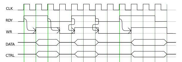
The user data path is 64-bits wide running at 125MHz. This would give the data path a peak bandwidth of 8Gbps. Packets are passed between modules using a fifo-like simple push interface with four signals: WR, RDY, DATA, and CTRL. The WR and RDY signals are each one bit wide while the CTRL is 8 bits wide and the DATA is 64 bits wide. Say module i_ wants to push a packet to module _i+1 . When i+1 is ready to accept some data, it will assert the RDY signal. Module i_ then puts the packet data on the DATA bus, sets the CTRL bus according to the data it is transmitting (the values of the CTRL bus are discussed later), and raises the WR signal whenever it is ready to send. Module _i+1 should be ready to latch the data transmitted the next clock cycle after asserting the RDY signal. If module i+1 cannot accept anymore data, it will deassert the RDY signal at least one clock cycle before the data should stop arriving. The figure below demonstrates a valid transaction.
 "Packet hand-off between two consecutive modules."
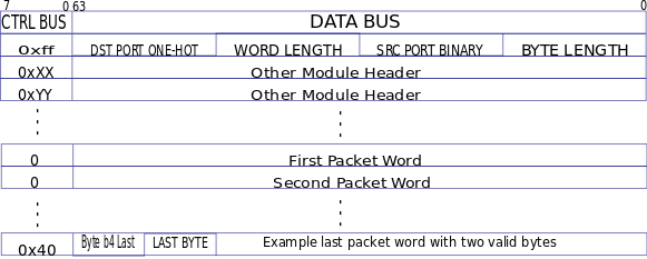
As a packet is processed by the modules in the data path, each module has the choice of either adding a 64-bit word to the beginning of the packet that contains the result of the processing or modifying a word that already exists. We call this word a module header. Modules that come later in the pipeline can use the information in the module header(s) to do further processing on the packet. In the reference designs we use only one module header that is modified by almost all modules in the pipeline.
The CTRL bus is used for two purposes. The first is to distinguish module headers from each other (see next paragraph), and to determine the end of the packet. The CTRL bus is non-zero for module headers and distinguishes module headers from each other when there are multiple module headers. When the actual packet received starts after the module headers, the CTRL bus is reset to 0, and then at the last word of the packet, the CTRL lines will indicate which byte is the last byte in the last word. This is done by setting a 1 in the position of the last byte. Note that the first byte of the packet is stored in the most significant byte position (byte 7, i.e. bits 63-56) of the first word of the packet, and so on. For example, if the last word has only 1 byte, then the last word will have the last byte in byte 7, and the CTRL word associated with that DATA word is 0b10000000. On the other hand, if the last word has six valid bytes (i.e. packet length in bytes mod 8 = 6) then the CTRL word that signifies the end-of-packet will be 0b00000100.
The Rx Queues create a module header when they receive a packet and prepend it to the beginning of the packet. The Rx queues store the length of the packet in bytes at the lowest 16 bits of the module header, the source port as a binary-encoded number (port 0 is MAC port 0 and port 1 is CPU port 0, ...) in bits 16–31, and the packet length in 64-bit words in bits 32–47. We call this module header the IOQ module header.
 "Format of a packet as it passes through the hardware pipeline."
The Input Arbiter selects an Rx queue to service and pushes a packet into the Output Port Lookup module without modifying the module header. The Output Port Lookup module decides which output port(s) a packet goes out of and writes the output ports selection as a one-hot-encoded number into bits 48–63 of the IOQ module header. This number has a one for every port the packet should go out on where port 0 is MAC0, port 1 is CPU0, port 2 is MAC1, ...
The Output Queues module looks at the IOQ module header to decide which output queue to store the packet in and uses the lengths from the IOQ module header to store the packet efficiently. After the packet is removed from its output queue and pushed into its destination Tx Queue, the IOQ module is finally removed before sending the packet out of the appropriate port. The diagram on the right shows the format of a packet as it passes through the reference pipeline.
Module authors may wish to incorporate registers that are accessible from the host within their modules. To simplify the process of adding modules the register interfaces of the modules are connected together in a pipeline manner instead of being connected in a star topology to a central arbiter. This greatly simplifies the process of adding a module to a design as it does not require the central arbiter to be modified.
The register pipeline is 32-bits wide and runs at 125 MHz. Each module should have two pairs of ports: one for incoming requests and one for outgoing replies. The following set of signals are the input signals for a single module: REG_REQ_IN, REG_ACK_IN, REG_RD_WR_L_IN, REG_ADDR_IN (23-bits), REG_DATA_IN (32-bits), REG_SRC_IN (2-bits). Equivalent signals ending in _OUT exist for the output port.
Register requests/replies are signaled by a high on REG_REQ_*. REG_REQ_* should only be high for a single clock cycle otherwise it indicates multiple register acccess. Note that a module is permitted to take more than one clock cycle to produce a reply but it should ensure that requests following the initial request are not dropped.) The REG_RD_WR_L_* signal indicates whether the transaction is a read (high) or a write (low). REG_ACK_* should be low when the request is generated and should only be brought high by the module responding to the request.
A module identifies whether it is the target of a request by inspecting the REG_ADDR_IN signal. If the address matches the address range assigned to the module then the module should process the request and generate a response. Once the module has completed any necessary processing it should raise REG_ACK_OUT, set REG_DATA_OUT to the correct value in the case of a read, and forward all other inputs to the outputs, all for a single cycle. If a module determines that it is not the target of a request then it should forward all inputs unmodified to the outputs on the next clock cycle.
The REG_SRC_* signals are used by register request initiators to identify the responses that are destined to the requestor. Each requestor should use a unique value as their source address.
There is a number of modules that are not described by the Reference Pipeline. These are the nf2_top and nf2_core modules which contain the Reference Pipeline as well as modules that are needed to generate the various clocks on the Virtex chip and interface with the PCI controller, SRAM, DRAM, ... These modules are outside the scope of this document. We invite you to help us extend this section of the documentation so that others may benefit from your experience.
The NFP contains several modules that can be used to add more features to your hardware design. The modules all exist under netfpga/lib/verilog. The module we will add in this walkthrough is a rate limiter which allows you to control the rate at which packets aresent out of a port. The module will be added into the user_data_path.v file.
Type the following:
~$ cd ~/NF2/projects/
~/NF2/projects$ cp -r reference_router/ rate_limited_router
~/NF2/projects$ mkdir rate_limited_router/src/udp
~/NF2/projects$ cp ../lib/verilog/user_data_path/reference_user_data_path/src/user_data_path.v rate_limited_router/src/udp/
We have now created a copy of the reference HCORR and made a local copy of the user_data_path.v file for overriding the reference one. The following assumes that you know Verilog. We will now connect four rate_limiter modules in the pipeline between the output_queues module and the MAC output ports of the user_data_path.v. The rate_limiter module is under netfpga/lib/verilog/rate_limiter. You can take a look at it for reference. After modifying netfpga/projects/rate_limited_router/src/udp/user_data_path.v to add the rate_limiter modules, the diff of the original user_data_path.v with the new one should look similar to below. You can find the modified user_data_path.v here:
234a235,251
>    //------- Rate limiter wires/regs ------
>    wire [CTRL_WIDTH-1:0]            rate_limiter_in_ctrl[0:3];
>    wire [DATA_WIDTH-1:0]            rate_limiter_in_data[0:3];
>    wire                             rate_limiter_in_wr[0:3];
>    wire                             rate_limiter_in_rdy[0:3];
>
>    wire [CTRL_WIDTH-1:0]            rate_limiter_out_ctrl[0:3];
>    wire [DATA_WIDTH-1:0]            rate_limiter_out_data[0:3];
>    wire                             rate_limiter_out_wr[0:3];
>    wire                             rate_limiter_out_rdy[0:3];
>
>    wire                             rate_limiter_in_reg_req[0:4];
>    wire                             rate_limiter_in_reg_ack[0:4];
>    wire                             rate_limiter_in_reg_rd_wr_L[0:4];
>    wire [`UDP_REG_ADDR_WIDTH-1:0]   rate_limiter_in_reg_addr[0:4];
>    wire [`CPCI_NF2_DATA_WIDTH-1:0]  rate_limiter_in_reg_data[0:4];
>    wire [UDP_REG_SRC_WIDTH-1:0]     rate_limiter_in_reg_src[0:4];
In the above we have added wires to connect the new modules.
360,363c377,380
<     .out_data_0       (out_data_0),
<     .out_ctrl_0       (out_ctrl_0),
<     .out_wr_0         (out_wr_0),
<     .out_rdy_0        (out_rdy_0),
---
>     .out_data_0       (rate_limiter_in_data[0]),
>     .out_ctrl_0       (rate_limiter_in_ctrl[0]),
>     .out_wr_0         (rate_limiter_in_wr[0]),
>     .out_rdy_0        (rate_limiter_in_rdy[0]),
370,373c387,390
<     .out_data_2       (out_data_2),
<     .out_ctrl_2       (out_ctrl_2),
<     .out_wr_2         (out_wr_2),
<     .out_rdy_2        (out_rdy_2),
---
>     .out_data_2       (rate_limiter_in_data[1]),
>     .out_ctrl_2       (rate_limiter_in_ctrl[1]),
>     .out_wr_2         (rate_limiter_in_wr[1]),
>     .out_rdy_2        (rate_limiter_in_rdy[1]),
380,383c397,400
<     .out_data_4       (out_data_4),
<     .out_ctrl_4       (out_ctrl_4),
<     .out_wr_4         (out_wr_4),
<     .out_rdy_4        (out_rdy_4),
---
>     .out_data_4       (rate_limiter_in_data[2]),
>     .out_ctrl_4       (rate_limiter_in_ctrl[2]),
>     .out_wr_4         (rate_limiter_in_wr[2]),
>     .out_rdy_4        (rate_limiter_in_rdy[2]),
390,393c407,410
<     .out_data_6       (out_data_6),
<     .out_ctrl_6       (out_ctrl_6),
<     .out_wr_6         (out_wr_6),
<     .out_rdy_6        (out_rdy_6),
---
>     .out_data_6       (rate_limiter_in_data[3]),
>     .out_ctrl_6       (rate_limiter_in_ctrl[3]),
>     .out_wr_6         (rate_limiter_in_wr[3]),
>     .out_rdy_6        (rate_limiter_in_rdy[3]),
414,419c431,436
<     .reg_req_out      (udp_reg_req_in),
<     .reg_ack_out      (udp_reg_ack_in),
<     .reg_rd_wr_L_out  (udp_reg_rd_wr_L_in),
<     .reg_addr_out     (udp_reg_addr_in),
<     .reg_data_out     (udp_reg_data_in),
<     .reg_src_out      (udp_reg_src_in),
---
>     .reg_req_out      (rate_limiter_in_reg_req[0]),
>     .reg_ack_out      (rate_limiter_in_reg_ack[0]),
>     .reg_rd_wr_L_out  (rate_limiter_in_reg_rd_wr_L[0]),
>     .reg_addr_out     (rate_limiter_in_reg_addr[0]),
>     .reg_data_out     (rate_limiter_in_reg_data[0]),
>     .reg_src_out      (rate_limiter_in_reg_src[0]),
Above: Instead of connecting the output ports of the output_queues module to the user_data_path output ports, connect them to the rate limiter modules. The same goes for the register ring connections.
437c454,525
<
---
>    generate
>       genvar i;
>       for (i=0; i<4; i=i+1) begin: gen_rate_limiters
>          rate_limiter #(
>            .DATA_WIDTH          (DATA_WIDTH),
>            .UDP_REG_SRC_WIDTH   (UDP_REG_SRC_WIDTH)
>          ) rate_limiter
>            (
>             .out_data                           (rate_limiter_out_data[i]),
>             .out_ctrl                           (rate_limiter_out_ctrl[i]),
>             .out_wr                             (rate_limiter_out_wr[i]),
>             .out_rdy                            (rate_limiter_out_rdy[i]),
>
>             .in_data                            (rate_limiter_in_data[i]),
>             .in_ctrl                            (rate_limiter_in_ctrl[i]),
>             .in_wr                              (rate_limiter_in_wr[i]),
>             .in_rdy                             (rate_limiter_in_rdy[i]),
>
>             // --- Register interface
>             .reg_req_in                         (rate_limiter_in_reg_req[i]),
>             .reg_ack_in                         (rate_limiter_in_reg_ack[i]),
>             .reg_rd_wr_L_in                     (rate_limiter_in_reg_rd_wr_L[i]),
>             .reg_addr_in                        (rate_limiter_in_reg_addr[i]),
>             .reg_data_in                        (rate_limiter_in_reg_data[i]),
>             .reg_src_in                         (rate_limiter_in_reg_src[i]),
>
>             .reg_req_out                        (rate_limiter_in_reg_req[i+1]),
>             .reg_ack_out                        (rate_limiter_in_reg_ack[i+1]),
>             .reg_rd_wr_L_out                    (rate_limiter_in_reg_rd_wr_L[i+1]),
>             .reg_addr_out                       (rate_limiter_in_reg_addr[i+1]),
>             .reg_data_out                       (rate_limiter_in_reg_data[i+1]),
>             .reg_src_out                        (rate_limiter_in_reg_src[i+1]),
>
>             // --- Misc
>             .clk                                (clk),
>             .reset                              (reset));
>       end // block: gen_rate_limiters
>    endgenerate
>
>    defparam gen_rate_limiters[0].rate_limiter.RATE_LIMIT_BLOCK_TAG = `RATE_LIMIT_0_BLOCK_TAG;
>    defparam gen_rate_limiters[1].rate_limiter.RATE_LIMIT_BLOCK_TAG = `RATE_LIMIT_1_BLOCK_TAG;
>    defparam gen_rate_limiters[2].rate_limiter.RATE_LIMIT_BLOCK_TAG = `RATE_LIMIT_2_BLOCK_TAG;
>    defparam gen_rate_limiters[3].rate_limiter.RATE_LIMIT_BLOCK_TAG = `RATE_LIMIT_3_BLOCK_TAG;
>
>    //--- Connect the wires from the rate limiters
>    assign out_data_0                = rate_limiter_out_data[0];
>    assign out_ctrl_0                = rate_limiter_out_ctrl[0];
>    assign out_wr_0                  = rate_limiter_out_wr[0];
>    assign rate_limiter_out_rdy[0]   = out_rdy_0;
>
>    assign out_data_2                = rate_limiter_out_data[1];
>    assign out_ctrl_2                = rate_limiter_out_ctrl[1];
>    assign out_wr_2                  = rate_limiter_out_wr[1];
>    assign rate_limiter_out_rdy[1]   = out_rdy_2;
>
>    assign out_data_4                = rate_limiter_out_data[2];
>    assign out_ctrl_4                = rate_limiter_out_ctrl[2];
>    assign out_wr_4                  = rate_limiter_out_wr[2];
>    assign rate_limiter_out_rdy[2]   = out_rdy_4;
>
>    assign out_data_6                = rate_limiter_out_data[3];
>    assign out_ctrl_6                = rate_limiter_out_ctrl[3];
>    assign out_wr_6                  = rate_limiter_out_wr[3];
>    assign rate_limiter_out_rdy[3]   = out_rdy_6;
>
>    assign udp_reg_req_in            = rate_limiter_in_reg_req[4];
>    assign udp_reg_ack_in            = rate_limiter_in_reg_ack[4];
>    assign udp_reg_rd_wr_L_in        = rate_limiter_in_reg_rd_wr_L[4];
>    assign udp_reg_addr_in           = rate_limiter_in_reg_addr[4];
>    assign udp_reg_data_in           = rate_limiter_in_reg_data[4];
>    assign udp_reg_src_in            = rate_limiter_in_reg_src[4];
Above: Add the rate limiter modules on each output port going to an Ethernet Tx queue. The register ring goes through each of the rate limiter modules. Note the defparams used to assign a register block for each rate limiter module. More on that is coming later.
Now all that is left is telling the build system that we want to include the rate limiter in compilation. All the library modules that a project uses are found in projects//include/lib_modules.txt. For the rate limited router, we will have the rate limiter module as well as all the modules that are normally used by the reference router. The modified lib_modules.txt looks as follows, where line 16 was added:
    1  io_queues/cpu_dma_queue
    2  io_queues/ethernet_mac
    3  input_arbiter/rr_input_arbiter
    4  nf2/generic_top
    5  nf2/reference_core
    6  user_data_path/generic_cntr_reg
    7  output_port_lookup/cam_router
    8  output_queues/sram_rr_output_queues
    9  sram_arbiter/sram_weighted_rr
   10  user_data_path/reference_user_data_path
   11  io/mdio
   12  cpci_bus
   13  dma
   14  user_data_path/udp_reg_master
   15  io_queues/add_rm_hdr
   16  rate_limiter
Note that the reference_user_data_path module is still mentioned in the lib_modules.txt even though we are overriding one of the files. This is because we would still like to use the other files that are in that module. The build environment will automatically handle the override and make sure that it uses the file in the project src dir instead of the library one. Also note that the build system only handles source files that are directlys under the src dir in the project directory and one level below it. So if you put a file under rate_limited_router/src/udp/some_dir/some_file.v it will not be included in the build.
All these library modules can be found under netfpga/projects/lib/verilog. Some library modules are only used for simulation, such as the testbench module. Some libraries offer alternatives such as the user_data_path module. If you look under netfpga/lib/verilog/user_data_path, you will find two directories, one has the user data path used for the buffer monitoring router, and one used in the reference router. If you have the full source package (the teacher/researcher package) you will also find an alternative for the output _port_lookup module: The cam_router which is a router using a CAM to perform LPM lookups and the learning_cam_switch which makes the NetFPGA act as a four-port learning switch. Note that the library modules that are not used in the reference NIC design and the reference IPv4 Router design have not received the same thorough testing as those that are. This includes the learning_cam_switch module and the rate_limiter module.
If you wish to add new source code (i.e. not from the library) to your project, you can simply put the new verilog files under the src dir in your project. You could also put them in a directory one level below the src directory. They will automatically be included for synthesis and simulation. Note that in case some files are only used for simulation, you will have to encapsulate the unsynthesizable code with synthesis translate_off and synthesis translate_on directives.
To add IP cores generated with the Xilinx's tool, you can do one of two things: Copy .xco file (recommended): Simply copy the .xco file from the directory where you generated the IP core to the /synth directory. The build environment will automatically regenerate the .v wrapper for simulation/synthesis and the .ngc or .edn needed for synthesis.
Copy the .ngc and .v files: Copy the generated .v files to your /src directory and the .ngc/.edn to your /synth directory. This will avoid reimplementing the core.
If you wish to add registers, you will need to create a module XML file for each module added to the design and modify the project XML file to include the additional modules. The high level description of the register system can be found in the Developers Guide. A more detailed description of the register system can be found on the Register System page.
The next step after writing the code is to simulate the design. We will use the same testbenches used for the router. These testbenches are defined under netfpga/projects/rate_limited_router/verif. Each directory contains a description of the packets to send, when to send them and which packets we expect to come out of the NetFPGA whether via DMA or Ethernet. The simulation environment also allows you to specify register reads and writes. Each testbench consists of a three files:
config.txt : specifies when a simulation should end.
run : generates packets and runs the simulation. Usually this should not be modified except for unusual circumstances such as simulation time parameter definitions.
make_pkts.pl : Perl script that generates all the packets and register requests.
test_router_short/make_pkts.pl is shown below ready for dissection:
File header. Nothing fancy.
    1	#!/usr/local/bin/perl -w
    2	# make_pkts.pl
    3	#
    4	#
Select the libraries to be used for simulation. Theses libraries provide functions to create/send/expect packets and to generate register requests. In particular, the SimLib encapsulates the nf_PCI_regread and the nf_PCI_regwrite functions which access registers. Writing of router specific tables the RouterLib can be used. These libraries and some others that are used for real hardware (as opposed to simulation) testing can be found under NF2/lib/Perl5/.
    7	use NF2::PacketGen;
    8	use NF2::PacketLib;
    9	use SimLib;
   10  use RouterLib;
Include the file that defines all register addresses.
11 require "reg_defines.ph";
Set the delay to send a packet. More information can be found in the comments and documentation in the libraries.
13 $delay = 2000;
Required lines to initiate the libraries.
   14	$batch = 0;
   15	nf_set_environment( { PORT_MODE => 'PHYSICAL', MAX_PORTS => 4 } );
   16
   17	# use strict AFTER the $delay, $batch and %reg are declared
   18	use strict;
   19	use vars qw($delay $batch %reg);
Define some variables for the tests:
   21	my $ROUTER_PORT_1_MAC = '00:ca:fe:00:00:01';
   22	my $ROUTER_PORT_2_MAC = '00:ca:fe:00:00:02';
   23	my $ROUTER_PORT_3_MAC = '00:ca:fe:00:00:03';
   24	my $ROUTER_PORT_4_MAC = '00:ca:fe:00:00:04';
   25
   26	my $ROUTER_PORT_1_IP = '192.168.1.1';
   27	my $ROUTER_PORT_2_IP = '192.168.2.1';
   28	my $ROUTER_PORT_3_IP = '192.168.3.1';
   29	my $ROUTER_PORT_4_IP = '192.168.4.1';
   30
   31	my $next_hop_1_DA = '00:fe:ed:01:d0:65';
   32	my $next_hop_2_DA = '00:fe:ed:02:d0:65';
   33
Initiate the DMA:
   34	# Prepare the DMA and enable interrupts
   35	prepare_DMA('@3.9us');
   36	enable_interrupts(0);
Write the registers to setup routes through the router:
   38	# Write the ip addresses and mac addresses, routing table, filter, ARP entries
   39	$delay = '@4us';
   40	set_router_MAC(1, $ROUTER_PORT_1_MAC);
   41	$delay = 0;
   42	set_router_MAC(2, $ROUTER_PORT_2_MAC);
   43	set_router_MAC(3, $ROUTER_PORT_3_MAC);
   44	set_router_MAC(4, $ROUTER_PORT_4_MAC);
   45
   46	add_dst_ip_filter_entry(0,$ROUTER_PORT_1_IP);
   47	add_dst_ip_filter_entry(1,$ROUTER_PORT_2_IP);
   48	add_dst_ip_filter_entry(2,$ROUTER_PORT_3_IP);
   49	add_dst_ip_filter_entry(3,$ROUTER_PORT_4_IP);
   50
   51	add_LPM_table_entry(0,'171.64.2.0', '255.255.255.0', '171.64.2.1', 0x04);
   52	add_LPM_table_entry(15, '0.0.0.0', '0.0.0.0', '171.64.1.1', 0x01);
   53
   54	# Add the ARP table entries
   55	add_ARP_table_entry(0, '171.64.1.1', $next_hop_1_DA);
   56	add_ARP_table_entry(1, '171.64.2.1', $next_hop_2_DA);
   57
   58	my $length = 100;
   59	my $TTL = 30;
   60	my $DA = 0;
   61	my $SA = 0;
   62	my $dst_ip = 0;
   63	my $src_ip = 0;
   64	my $pkt;
   65
Send the first packet into port 1 (MAC port 0). Note that the ports in the simulation libraries are all defined starting from 1 as opposed to 0.
   70	$delay = '@80us';
   71	$length = 64;
   72	$DA = $ROUTER_PORT_1_MAC;
   73	$SA = '01:55:55:55:55:55';
   74	$dst_ip = '171.64.2.7';
   75	$src_ip = '171.64.8.1';
Create the packet:
76 $pkt = make_IP_pkt($length, $DA, $SA, $TTL, $dst_ip, $src_ip);
Send it in:
77 nf_packet_in(1, $length, $delay, $batch, $pkt);
Create the packet that we expect to see coming out of port 2 (MAC port 1):
   79	$DA = $next_hop_2_DA;
   80	$SA = $ROUTER_PORT_2_MAC;
   81	$pkt = make_IP_pkt($length, $DA, $SA, $TTL-1, $dst_ip, $src_ip);
   82	nf_expected_packet(2, $length, $pkt);
Create a new packet from a different port that is destined for the router itself. The packet should be sent to the CPU via DMA.
   88	$length = 60;
   89	$DA = $ROUTER_PORT_2_MAC;
   90	$SA = '02:55:55:55:55:55';
   91	$dst_ip = $ROUTER_PORT_1_IP;
   92	$src_ip = '171.64.9.1';
   93	$pkt = make_IP_pkt($length, $DA, $SA, $TTL, $dst_ip, $src_ip);
   94	nf_packet_in(2, $length, '@82us', $batch,  $pkt);
Specify that we expect the packet to come on DMA port 2 (a.k.a nf2c1):
96 nf_expected_dma_data(2, $length, $pkt);
Now send a packet out from nf2c1. This also says that we should expect the same packet to come out of MAC port 1:
98   $delay = '@100us';
99    PCI_create_and_send_pkt(2, $length);
The rest of the lines till 163 test different size packets. After that there's some code that generates all this info and puts it in files. The rest should not be changed in general:
  163	# '''*********''' Finishing Up - need this in all scripts ! '''**************************'''
  164	my $t = nf_write_sim_files();
  165	print  "--- make_pkts.pl: Generated all configuration packets.\n";
  166	printf "--- make_pkts.pl: Last packet enters system at approx %0d microseconds.\n",($t/1000);
  167	if (nf_write_expected_files()) {
  168	  die "Unable to write expected files\n";
  169	}
  170
  171	nf_create_hardware_file('LITTLE_ENDIAN');
  172	nf_write_hardware_file('LITTLE_ENDIAN');
Now to run the simulation, we need to make sure that our environment is set. Make sure that your NF_ROOT environment variable points to the path where the netfpga directory is (e.g. ~/netfpga) and that your NF_DESIGN_DIR points to ${NF_ROOT}/projects/rate_limited_router. Also make sure that you are sourcing the settings from ${NF_ROOT}/bin/nf2_profile or ${NF_ROOT}/bin/nf2_cshrc depending on your shell. Of course we will need to have Modelsim installed. To run the simulations:
nf_run_test.pl --major router --minor short
The test should then generate the packets and register requests and run the simulation in console mode. When the test is done, it will search for the word ERROR in the log to find out if an error occurred and let you know. If you would like to run the test in a GUI to view the waveforms and have complete control over the simulation, you can add the --gui switch to the command. For more information on other options type:
nf_run_test.pl --help
After you run the simulation you should see output similar to what is seen below (this is only the last part):
...
# Timecheck: 493645.00ns
#               500100 Simulation has reached finish time - ending.
# ** Note: $finish    : /home/jnaous/mckeown/NF2/new_tree/lib/verilog/testbench/target32.v(616)
#    Time: 500100 ns  Iteration: 0  Instance: /testbench/target32
--- Simulation is complete. Validating the output.
        Comparing simulation output for port 1 ...
        Port 1 matches [0 packets]
        Comparing simulation output for port 2 ...
        Port 2 matches [4 packets]
        Comparing simulation output for port 3 ...
        Port 3 matches [0 packets]
        Comparing simulation output for port 4 ...
        Port 4 matches [0 packets]
        Comparing simulation output for DMA queue 1 ...
        DMA queue 1 matches [0 packets]
        Comparing simulation output for DMA queue 2 ...
        DMA queue 2 matches [2 packets]
        Comparing simulation output for DMA queue 3 ...
        DMA queue 3 matches [0 packets]
        Comparing simulation output for DMA queue 4 ...
        DMA queue 4 matches [0 packets]
--- Test  PASSED
Test test_router_short passed!
------------SUMMARY---------------
PASSING TESTS:
                test_router_short
FAILING TESTS:
TOTAL: 1 PASS: 1  FAIL: 0
Implementing the design is a very simple process:
cd rate_limited_router/synth
make
When make is done, you should have a bitfile called nf2_top_par.bit that should be downloaded to the NetFPGA to run. To download it, use:
nf_download ./nf2_top_par.bit
The synthesis process uses Smartguide by default when rebuilding a project. In cases where the netlist is changed dramatically between synthesis runs, or where the place and route process does not manage to route the nets to meet timing, Smartguide will produce results that fail to meet timing or will take a very very long time to finish (and still fail to meet timing). In these cases, you can disable Smartguide by adding the following line before the include in the synth/Makefile:
USE_SMARTGUIDE := 0Also, by default, map uses the timing switch to improve timing. This can in some cases lead to weird errors during the map process. To disable the use of the timing switch, add the following line to /synth/Makefile:
TIMING := 0You can set these switches to 1 or just comment them out to re-enable Smartguide or timing.
A full Perl library is available to test the actual hardware. The library netfpga/lib/Perl5/TestLib.pm contains many functions that can be used to send/receive packets and read/write registers. For more information on using these libraries, you can look at the various regression tests under netfpga/projects/reference_router/regress as well as looking through the library code to see which functions are available and read the comments to know what they do. We invite you to help us by expanding this section or submitting patches that provide additional documentation on using the Perl library.
- You can go through the Reference NIC Walkthrough if you are interested in using the NetFPGA as a network interface card
- You can go through the SCONE Software Walkthrough if you are interested in writing software for the NetFPGA to run in the host
- You can go through the Linux Router Kit Walkthrough if you are interested in using the NetFPGA as a high performance router
- You can go through the Buffer Monitoring System Walkthrough if you are interested in how to test/measure the lengths of buffers.
- Return to the Main Guide