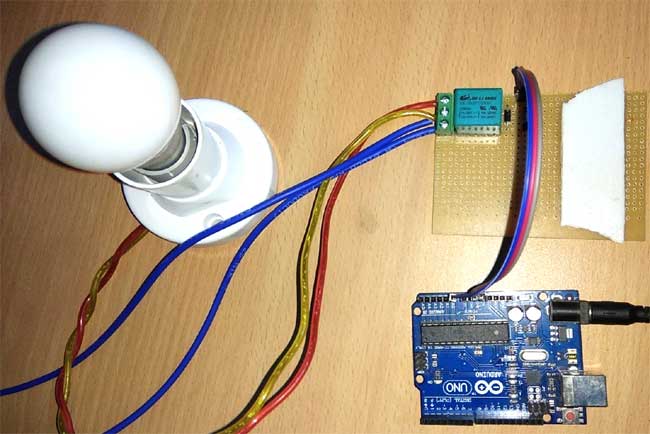
This Arduino Relay Control Projectdemonstrates how to control AC appliances using Arduino and a relay module. Instead of blinking a simple LED, this tutorial shows how to control an AC bulb by interfacing a relay with Arduino. This is a fundamental project for anyone looking to control high-voltage AC devices using low-voltage DC microcontroller circuits.
Original Tutorial: Arduino Relay Control - Circuit Digest Arduino Projects &Tutorials: Arduino Projects
- Control AC appliances with Arduino
- Simple relay switching mechanism
- Basic transistor-based relay driver circuit
- Safety implementation with a protection diode
- Automated ON/OFF control with programmable delays
| Component | Quantity | Description |
|---|---|---|
| Arduino (Uno/Nano) | 1 | Microcontroller board |
| 5V/6V Relay | 1 | Electromagnetic switch |
| BC547 Transistor | 1 | NPN transistor for switching |
| 1kΩ Resistor | 1 | Base resistor for transistor |
| 1N4007 Diode | 1 | Flyback protection diode |
| AC Bulb/Appliance | 1 | Load to be controlled |
| Breadboard/PCB | 1 | Circuit assembly |
| Jumper Wires | Several | Connections |
| 12V Power Supply | 1 | External power for relay |
| Screw Terminal | 1 | AC connections |
- Arduino Pin A0 → 1kΩ Resistor → BC547 Base
- BC547 Collector → Relay Coil (+)
- BC547 Emitter → Ground
- Relay Coil (-) → Ground
- 1N4007 Diode → Parallel to Relay Coil (Cathode to +ve)
- AC Live → Relay COM
- Relay NO → AC Bulb
- AC Neutral → AC Bulb
A relay is an electromagnetic switch controlled by a small current to switch much larger currents. The relay used is a Single Pole Double Throw (SPDT) type with five terminals:
- COM (Common): Central switching terminal
- NO (Normally Open): Connected to COM when relay is energized
- NC (Normally Closed): Connected to COM when relay is de-energized
- Coil Terminals: For control voltage (5V/6V)
- Arduino sends HIGH signal to pin A0
- Current flows through 1kΩ resistor to BC547 base
- BC547 transistor turns ON, completing relay coil circuit
- Relay energizes, connecting COM to NO
- AC bulb turns ON
- Process reverses when Arduino sends LOW signal
- 1N4007 Diode: Protects against back EMF when relay coil is de-energized
- 1kΩ Resistor: Limits base current to protect transistor
// Arduino Relay Control Code
#define relay A0
#define interval 1000

void setup() {
  pinMode(relay, OUTPUT);
}

void loop() {
  digitalWrite(relay, HIGH);  // Turn relay ON
  delay(interval);            // Wait 1 second
  digitalWrite(relay, LOW);   // Turn relay OFF
  delay(interval);            // Wait 1 second
}- Pin A0 is configured as output for relay control
- digitalWrite(relay, HIGH) energizes the relay
- digitalWrite(relay, LOW) de-energizes the relay
- delay(interval) creates 1-second delays between switching
- Connect the relay driver circuit on breadboard
- Wire Arduino pin A0 to the transistor base through 1kΩ resistor
- Connect the protection diode across relay coil
- Wire the AC load through relay contacts
- Ensure proper grounding
- Open Arduino IDE
- Copy the provided code
- Select correct board and port
- Upload the code to Arduino
- Power up the circuit
- Observe AC bulb blinking with 1-second intervals
- Monitor relay clicking sound during operation
- Always disconnect AC power when making connections
- Use proper insulation for AC terminals
- Double-check all connections before powering up
- Never touch AC terminals when circuit is powered
- Use appropriate fuses and circuit breakers
- Home Automation: Light and appliance control
- Industrial Control: Motor and equipment switching
- IoT Projects: Remote appliance control
- Timer Circuits: Automated switching systems
- Security Systems: Alarm and notification devices
| Problem | Possible Cause | Solution |
|---|---|---|
| Relay not switching | Transistor not conducting | Check base resistor connection |
| Continuous relay chatter | Missing flyback diode | Install 1N4007 across coil |
| Arduino resets | Back EMF damage | Ensure diode polarity is correct |
| No AC load control | Relay contacts wiring | Verify COM, NO, NC connections |
- Manual Switch Control: Add physical buttons
- Sensor Integration: Light/motion sensor triggering
- Multiple Relay Control: Expand to relay modules
- Wireless Control: Add WiFi/Bluetooth capability
- Feedback Systems: Current/voltage monitoring
// Example: Multiple relay control
#define relay1 A0
#define relay2 A1
#define relay3 A2

// Example: Sensor-based control
int sensorValue = analogRead(A3);
if (sensorValue > threshold) {
  digitalWrite(relay, HIGH);
}- ESP32 Home Automation Systems
- IoT-based Appliance Control
- Smart Switch Implementations
- Industrial Automation Controllers
This project is open-source and available for educational and commercial use.
Contributions are welcome! Please feel free to submit pull requests or open issues for improvements.
Note: This project involves working with AC mains voltage. Please ensure you have proper knowledge of electrical safety before attempting this project. When in doubt, consult with a qualified electrician.