-
Notifications
You must be signed in to change notification settings - Fork 109
New issue
Have a question about this project? Sign up for a free GitHub account to open an issue and contact its maintainers and the community.
By clicking “Sign up for GitHub”, you agree to our terms of service and privacy statement. We’ll occasionally send you account related emails.
Already on GitHub? Sign in to your account
path_extrude() behavior incorrect in latest release(s) but correct in v1.0.0 #5
Comments
|
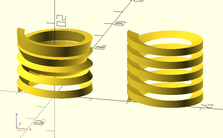
Actually, it's correct behavior of If you want to extrude a shape along a path precisely, providing enough information about how to rotate sections is necessary. If you want to extrude a shape along a helix, include <rotate_p.scad>;
include <polysections.scad>;
include <helix.scad>;
include <cross_sections.scad>;
include <helix_extrude.scad>;
r = 10;
fa = 2;
shape_pts = [
[0,0],
[-3, 1],
[0, 2]
];
$fn = 360 / fa;
helix_extrude(
shape_pts,
radius = r,
levels = 5,
level_dist = 3.6,
vt_dir = "SPI_UP"
);If you have only points, what If you still want to use include <rotate_p.scad>;
include <polysections.scad>;
include <path_extrude.scad>;
r = 10;
fa = 2;
shape_pts = [
[0,0],
[3, 1],
[0, 2]
];
path_pts = [
for(a = [0:fa:360 * 5])
[-r * cos(a), r * sin(a), a/100]
];
path_extrude(
shape_pts,
path_pts,
twist = 100 // adjust it
);In this situation, you provide information which path points do not provide. You think it's a bug in (Even though old algorithm of |
|
I add a include <rotate_p.scad>;
include <polysections.scad>;
include <path_extrude.scad>;
r = 10;
fa = 2;
shape_pts = [
[0,0],
[3, 1],
[0, 2]
];
path_pts = [
for(a = [0:fa:360 * 5])
[-r * cos(a), r * sin(a), a/100]
];
path_extrude(
shape_pts,
path_pts,
method = "AXIS_ANGLE" // default
);
translate([r * 3, 0, 0]) path_extrude(
shape_pts,
path_pts,
method = "EULER_ANGLE"
);
include <shape_pentagram.scad>;
include <rotate_p.scad>;
include <polysections.scad>;
include <path_extrude.scad>;
include <torus_knot.scad>;
p = 2;
q = 3;
phi_step = 0.05;
star_radius = 0.5;
pts = torus_knot(p, q, phi_step);
shape_pentagram_pts = shape_pentagram(star_radius);
// not closed perfectly
translate([-8, 0, 0]) path_extrude(
shape_pentagram_pts,
concat(pts, [pts[0]]),
closed = true,
method = "AXIS_ANGLE"
);
// adjust it
path_extrude(
shape_pentagram_pts,
concat(pts, [pts[0]]),
closed = true,
twist = 188,
method = "AXIS_ANGLE"
);
// "EULER_ANGLE" is easy in this situation
translate([0, 8, 0]) path_extrude(
shape_pentagram_pts,
concat(pts, [pts[0]]),
closed = true,
method = "EULER_ANGLE"
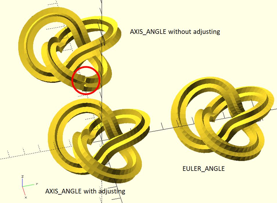
);If no problem, the new parameter |
|
Could you explain what EULER/AXIS_ANGLE are actually doing in math terms?
You seem to suggest that AXIS_ANGLE is yielding a non-function property, i.e. two same input values yielding different outputs.
…On May 31, 2019 2:46:36 AM UTC, Justin Lin ***@***.***> wrote:
I add a `method` parameter to `path_extrude`. It accepts two values,
`"AXIS_ANGLE"` and `"EULER_ANGLE"`.
```openscad
include <rotate_p.scad>;
include <polysections.scad>;
include <path_extrude.scad>;

r = 10;
fa = 2;

shape_pts = [
    [0,0],
    [3, 1],
    [0, 2]
];

path_pts = [
    for(a = [0:fa:360 * 5])
    [-r * cos(a), r * sin(a), a/100]
];

path_extrude(
    shape_pts,
    path_pts,
    method = "AXIS_ANGLE"  // default
);

translate([r * 3, 0, 0]) path_extrude(
    shape_pts,
    path_pts,
    method = "EULER_ANGLE"
);
```

`"AXIS_ANGLE"` is the default value because `"EULER_ANGLE"` may have an
abrupt when the path is exactly vertical. It happened in [(older)
Blender](https://download.blender.org/documentation/htmlI/ch09s04.html),
too.

`"EULER_ANGLE"`, however, generates the same section at the same point.
This means that you don't have to adjust sections if you want to
extrude along a closed path. It's an advantage when extruding. For
example:
```openscad
include <shape_pentagram.scad>;
include <rotate_p.scad>;
include <polysections.scad>;
include <path_extrude.scad>;
include <torus_knot.scad>;

p = 2;
q = 3;
phi_step = 0.05;
star_radius = 0.5;

pts = torus_knot(p, q, phi_step);

shape_pentagram_pts = shape_pentagram(star_radius);

// not closed perfectly
translate([-8, 0, 0]) path_extrude(
    shape_pentagram_pts,
    concat(pts, [pts[0]]),
    closed = true,
    method = "AXIS_ANGLE"
);

// adjust it
path_extrude(
    shape_pentagram_pts,
    concat(pts, [pts[0]]),
    closed = true,
    twist = 188,
    method = "AXIS_ANGLE"
);

// "EULER_ANGLE" is easy in this situation
translate([0, 8, 0]) path_extrude(
    shape_pentagram_pts,
    concat(pts, [pts[0]]),
    closed = true,
    method = "EULER_ANGLE"
);
```

If no problem, the new parameter `method` will be documented in the
next release.
--
You are receiving this because you authored the thread.
Reply to this email directly or view it on GitHub:
#5 (comment)
--
Sent from my Android device with K-9 Mail. Please excuse my brevity.
|
|
|
|
Thanks for the suggestion. I agree with you that indeed (rotation)
information is missing. This naturally leads to the questions what the
default values that it assumes are, and how this missing information to the
function (path_extrude) can be added so as to get the expected result?
…On Thu, May 30, 2019 at 4:15 AM Justin Lin ***@***.***> wrote:
Actually, it's correct behavior of path_extrude in dotSCAD 1.1 or later
because it takes different algorithm for rotating sections from path points.
If you want to extrude a shape along a path precisely, providing enough
information about how to rotate sections is necessary. If you want to
extrude a shape along a helix, helix_extrude is more suitable because it
knows how to dig out necessary data for rotating sections precisely.
include <rotate_p.scad>;include <polysections.scad>;include <helix.scad>;include <cross_sections.scad>;include <helix_extrude.scad>;
r = 10;
fa = 2;
shape_pts = [
[0,0],
[-3, 1],
[0, 2]
];
$fn = 360 / fa;
helix_extrude(
shape_pts,
radius = r,
levels = 5,
level_dist = 3.6,
vt_dir = "SPI_UP"
);
[image: helix1]
<https://user-images.githubusercontent.com/3424741/58603509-9d409600-82c3-11e9-92c5-e3a57124629c.JPG>
If you have only points, what path_extrude can do is to *guess* data
about rotations. The different algorithm will dig out different data.
path_extrude in dotSCAD 1.0 just has the result you want but has an
obvious bug in some situation. (See issue #3
<#3>). The bug is fixed after
v1.1.
If you still want to use path_extrude, one way to get what you want is
using the twist parameter. For example:
include <rotate_p.scad>;include <polysections.scad>;include <path_extrude.scad>;
r = 10;
fa = 2;
shape_pts = [
[0,0],
[3, 1],
[0, 2]
];
path_pts = [
for(a = [0:fa:360 * 5])
[-r * cos(a), r * sin(a), a/100]
];
path_extrude(
shape_pts,
path_pts,
twist = 100 // adjust it
);
[image: helix]
<https://user-images.githubusercontent.com/3424741/58603462-71251500-82c3-11e9-93df-9ca673c5e1f9.JPG>
In this situation, you provide information which path points do not
provide. You think it's a bug in path_extrude after dotSCAD 1.1 because
your brain has information that path points do not provide.
(Even though old algorithm of path_extrude has an obvious bug, it has
some benefits in some situations. I'm still considering whether I should
provide an option for users to switch these two algorithms in the later
version.)
—
You are receiving this because you authored the thread.
Reply to this email directly, view it on GitHub
<#5?email_source=notifications&email_token=AC7BXHE5PVGYWNAYCS7EE7LPX42EDA5CNFSM4HQZLE62YY3PNVWWK3TUL52HS4DFVREXG43VMVBW63LNMVXHJKTDN5WW2ZLOORPWSZGODWREV5Q#issuecomment-497175286>,
or mute the thread
<https://github.com/notifications/unsubscribe-auth/AC7BXHFNMSIIOPZZEZWDP73PX42EDANCNFSM4HQZLE6Q>
.
|
|
If we have enough information (shape points, path points and angles basically), |
|
For a non-mathematician, like myself, this description is a bit too terse.
Could you elaborate a bit on which two points you are referring to for
EULER_ANGLE?
The same question for the "three points" regarding AXIS_ANGLE.
By the way, I really like your openscad library. It's one of the best ones
I've seen so far.
I made some small changes to make it work properly with openscad-2019.05,
which I will detail on later. Do you accept pull requests?
…On Fri, May 31, 2019 at 10:24 AM Justin Lin ***@***.***> wrote:
"EULER_ANGLE takes one vector between two points to dig out Euler angles
<https://en.wikipedia.org/wiki/Euler_angles> required when rotating
sections.
AXIS_ANGLE takes three points to determinate two vectors used for
rotating sections. The sections are rotated by Quaternion
<https://en.wikipedia.org/wiki/Quaternion>. A simple figure is shown in issue
3 <#3> for explaining how it
works.
<https://user-images.githubusercontent.com/3424741/56887837-30a86080-6aa5-11e9-8505-fa7fdace2de4.JPG>
"AXIS_ANGLE " is preferred because it doesn't generate an abrupt for most
situations.
—
You are receiving this because you authored the thread.
Reply to this email directly, view it on GitHub
<#5?email_source=notifications&email_token=AC7BXHABGM5LYL72OLD6B63PYDODJA5CNFSM4HQZLE62YY3PNVWWK3TUL52HS4DFVREXG43VMVBW63LNMVXHJKTDN5WW2ZLOORPWSZGODWUSBGY#issuecomment-497623195>,
or mute the thread
<https://github.com/notifications/unsubscribe-auth/AC7BXHGWAEOL2C6K3AIEHKDPYDODJANCNFSM4HQZLE6Q>
.
|
Euler angleAxis angleIf you still don't understand, I'll suggest you read the links I provided and read source code for details. OpenSCAD-2019.05 was published just a few days ago so it's not urgent to leverage its new features in dotSCAD for compatibility. For those annoy warnings when using OpenSCAD-2019.05 and dotSCAD 1.1/1.0, you may use dotSCAD 1.2. It's fixed. The new version which works properly with OpenSCAD-2019.05 will be a target at dotSCAD 2.0. Please stay tuned. |
|
Thanks for the elaboration. This makes sense.
Can you explain under which conditions the "closing mismatch" with
AXIS_ANGLE occurs?
I read some of the wikipedia documentation, and it's much clearer now.
Can't you avoid the problems of both proposed methods by another method
that simply:
1. uses the vector between point x_n and x_(n+1) as normal vector of the
plane that contains the 2D polygon,
2. uses a "minimal energy" rotation method to provide the third degree of
freedom.
The first property is easy to implement. The second is a bit more difficult
but I think that if you take any point p1 of the 2D polygon centered at
x_n, the rotational energy is minimized if the same polygon point around
x_(n+1) has minimal distance. This looks like a problem for which a
closed-form solution exists, although I don't know one. You might know.
Perhaps the second property can be implied by a smart implementation of the
first property.
Any thoughts?
…On Sat, Jun 1, 2019 at 3:17 AM Justin Lin ***@***.***> wrote:
Euler angle
[image: euler]
<https://user-images.githubusercontent.com/3424741/58741530-82e5f400-844c-11e9-92db-a114e50eb9c9.JPG>
Axis angle
[image: axis]
<https://user-images.githubusercontent.com/3424741/58741535-9002e300-844c-11e9-99fa-06f72de06597.JPG>
If you still don't understand, I'll suggest you read the links I provided
and read source code for details.
OpenSCAD-2019.05 was published just a few days ago so it's not urgent to
leverage its new features in dotSCAD for compatibility. I've fixed those
annoy warnings when using OpenSCAD-2019.05 and dotSCAD 1.1/1.0.
*The new version which works properly with OpenSCAD-2019.05 is a target at
dotSCAD 2.0.* Please stay tuned.
—
You are receiving this because you authored the thread.
Reply to this email directly, view it on GitHub
<#5?email_source=notifications&email_token=AC7BXHCUKZRJX325Y3HWQXLPYHEZ7A5CNFSM4HQZLE62YY3PNVWWK3TUL52HS4DFVREXG43VMVBW63LNMVXHJKTDN5WW2ZLOORPWSZGODWWVZJQ#issuecomment-497900710>,
or mute the thread
<https://github.com/notifications/unsubscribe-auth/AC7BXHDSJC4RUT72DDARNMLPYHEZ7ANCNFSM4HQZLE6Q>
.
|
|
If you really know what the problem is when using Euler angles and what the axis-angle rotation is. You'll know when "closing mismatch" happens. If you really think it's simple to use the methods you list and easy to implement, you may try it by yourself. I currently have no idea about how to improve the situation. Actually, what you mentioned in the label 1 have been done in As for the label 2, the same conclusion as I've said before.
I think your biggest problem is, why do you think generating the same section at the same point is the correct behavior? dotSCAD is an opensource library. If you come out with a solution to solve the problem, just do it. Don't just say that something is easy or simple to implement. |

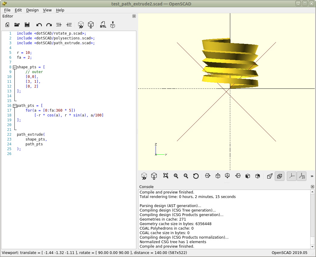
Instead of a regular thread, I see a gradually rotated thread for increasing z.
With release v1.0.0 the behavior was correct, but with release v1.2.0 (and possibly older releases) the behavior is incorrect.
The code that shows this behavior is:
include <dotSCAD/rotate_p.scad>;
include <dotSCAD/polysections.scad>;
include <dotSCAD/path_extrude.scad>;
r = 10;
fa = 2;
shape_pts = [
// outer
[0,0],
[3, 1],
[0, 2]
];
path_pts = [
for(a = [0:fa:360 * 5])
[-r * cos(a), r * sin(a), a/100]
];
path_extrude(
shape_pts,
path_pts
);
The correct output result is shown below.
The incorrect output result is shown below.

The text was updated successfully, but these errors were encountered: