In this assignment we were tasked with lighting on the led on the metro board using the built in led called the Neopixle.
import board
import neopixel

dot = neopixel.NeoPixel(board.NEOPIXEL, 1)
dot.brightness = 0.5

print("Make it red!")

while True:
    dot.fill((0, 0, 255))
Credit: https://github.com/Jpark27614
The Neopixle didn't require wiring because it was a built in LEDto the board
The hardest part of this challenge was getting the libraries to work as the boards had an outdated lib folder and didnt contain the same
In this assignment we were tasked with controling a servo and creating the "sweep" function which is a function that moves the servo between 0 and 180 degrees. The advanced version asked the servo to be controlled with a buton.
import board
import time
import pwmio
from adafruit_motor import servo
from digitalio import DigitalInOut, Direction, Pull

pwm = pwmio.PWMOut(board.A1, duty_cycle=2 ** 15, frequency=50)

btn1 = DigitalInOut(board.D8)
btn1.direction = Direction.INPUT
btn1.pull = Pull.UP
#definitions for button pins

btn2 = DigitalInOut(board.D9)
btn2.direction = Direction.INPUT
btn2.pull = Pull.UP


my_servo = servo.Servo(pwm)
angle = 0
lock1 = False
lock2 = False


while True:
    if not  btn2.value and lock1 == False:
        lock1 = True
        lock2 = False
        for angle in range(0, 180, 5):  # 0 - 180 degrees, 5 degrees at a time.
            my_servo.angle = angle
            print(angle)


    if not btn1.value and lock2 == False:
        lock1 = False # locks the turn so that you dont have to
        lock2 = True
        for angle in range(180, 0, -5): # 180 - 0 degrees, 5 degrees at a time.
            my_servo.angle = angle
            print(angle)

    time.sleep(0.1) # sleep for debounce

This assignment was a good introduction into how buttons work and how the overall formatting/syntax of python contrasts with C++. It was also a good way to see elements of the arduino work space such as pin definitions.
In this assignment we were tasked with cycling through a color spectrum based on the distance we read from the ultrasonic sensor.

import board
import time
import pwmio
from digitalio import DigitalInOut, Direction, Pull
import board
from lcd.lcd import LCD
from lcd.i2c_pcf8574_interface import I2CPCF8574Interface

i2c = board.I2C()
lcd = LCD(I2CPCF8574Interface(i2c, 0x3f), num_rows=2, num_cols=16)
#object decelerations

btn = DigitalInOut(board.D8)
btn.direction = Direction.INPUT
btn.pull = Pull.DOWN

switch = DigitalInOut(board.D7)
switch.direction = Direction.INPUT
switch.pull = Pull.DOWN
#Declaring the pins pull down as to detect signal change

changeVal =1
printedVal =0
btnState = False
#Global Vars :(

def switchManager():
    if switch.value ==True:
        return  1
    else:
       return  -1
    #manages the switch and the value multiplier.

def buttonManager():
    global printedVal
    global btnState
    global changeVal
    changeVal = switchManager()
    if btn.value != btnState:
        #catches the loop and halts activation untill button is released.
        btnState = False
    if btn.value == True and btnState == False:
        #changes the value(printedVal) based on switchManager()/switch
        printedVal += changeVal
        btnState = True
    #controls the button press as to only allow one activation after press

def lcdUpdate(change,print):
    lcd.print(f" Value:{print}\n switch:{change}")
    time.sleep(.1)
    lcd.clear()
    #Just prints the values to the lcd using f String.

while True:
    buttonManager()
    lcdUpdate(changeVal,printedVal)

    print(f"printed Value:{printedVal}")
    print(f"changeVal:{switchManager()}")


#By Paul WederPictures / Gifs of your work should go here. You need to communicate what your thing does.


Overall this assignment was useful when continuing to implement new/old features into python. Some include the map function which was vital when creating this code. I learned new things such as how to read values from the ultrasonic sensor, how to use F strings and sort your code outside of the TRUE loop.
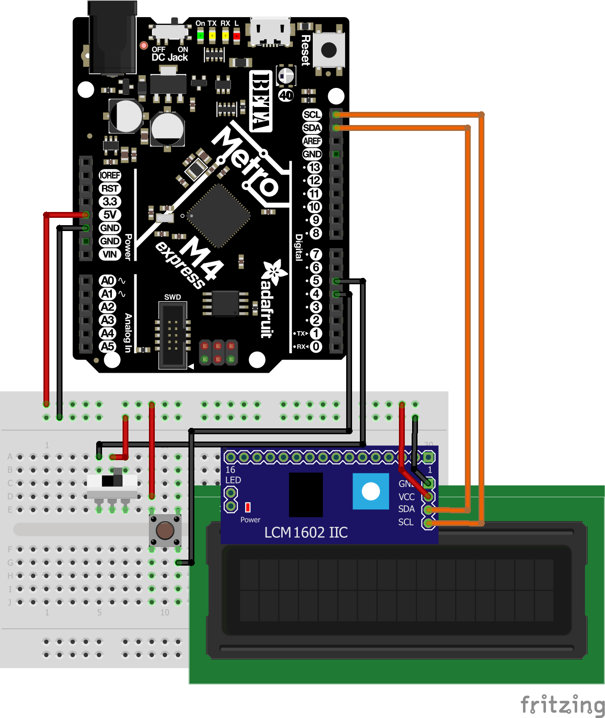
In this assignment we were tasked with changing the the number printed to the LCD with a button making the value go up and if the switch is flipped make the value go down.
import board
import time
import pwmio
from digitalio import DigitalInOut, Direction, Pull
import board
from lcd.lcd import LCD
from lcd.i2c_pcf8574_interface import I2CPCF8574Interface

i2c = board.I2C()
lcd = LCD(I2CPCF8574Interface(i2c, 0x3f), num_rows=2, num_cols=16)
#object declerations

btn = DigitalInOut(board.D8)
btn.direction = Direction.INPUT
btn.pull = Pull.DOWN

switch = DigitalInOut(board.D7)
switch.direction = Direction.INPUT
switch.pull = Pull.DOWN
#Declaring the pins pull down as to detect signal change

changeVal =1
printedVal =0
btnState = False
#Global Vars :(

def switchManager():
    if switch.value ==True:
        return  1
    else:
       return  -1
    #manages the switch and the value multiplier.

def buttonManager():
    global printedVal
    global btnState
    global changeVal
    changeVal = switchManager()
    if btn.value != btnState:
        #catches the loop and halts activation untill button is released.
        btnState = False
    if btn.value == True and btnState == False:
        #changes the value(printedVal) based on switchManager()/switch
        printedVal += changeVal
        btnState = True
    #controls the button press as to only allow one activation after press

def lcdUpdate(change,print):
    lcd.print(f" Value:{print}\n switch:{change}")
    time.sleep(.1)
    lcd.clear()
    #Just prints the values to the lcd using f String.

while True:
    buttonManager()
    lcdUpdate(changeVal,printedVal)

    print(f"printed Value:{printedVal}")
    print(f"changeVal:{switchManager()}")


#By Paul Weder

Good reintroduction into lcd screens and managing the object. Reading the documentation on the object was very useful to understand what was actually going on as i had issues with clearing the LCD at the right time.
In this assignment we were tasked with controlling a motor using a transistor. We would control this motor using output gained from a Potentiometer.
import board
from analogio import AnalogIn, AnalogOut
import simpleio
import pwmio

control = pwmio.PWMOut(board.D8, duty_cycle = 2 ** 15)


pot = AnalogIn(board.A0)

while True:
    print(int(pot.value))
    control.duty_cycle = simpleio.map_range(pot.value,0,65355,0,255)

# by Paul wederOverall this assignment was a good way for me to learn how transistors work and how not to mistake it for a temperature sensor. The code was very easy as it was just a mapping of the pot to the pwm output. Troubles were with figuring out the order of the in my case MOSFET transistor and how to read documentation that wasn't created by Adafruit especially on gate drain and source the 3 pins coming from the transistor.