Binary code of N digits can be used to store 2N distinct elements of coded information. This is what encoders and decoders are used for. Encoders convert 2N lines of input into a code of N bits and Decoders decode the N bits into 2N lines.
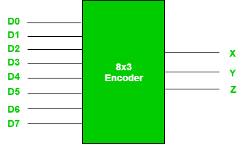
Encoders – An encoder is a combinational circuit that converts binary information in the form of a 2N input lines into N output lines, which represent N bit code for the input. For simple encoders, it is assumed that only one input line is active at a time. As an example, let’s consider Octal to Binary encoder. As shown in the following figure, an octal-to-binary encoder takes 8 input lines and generates 3 output lines.

An octal to binary encoder can be represented using a logical expression. Each octal digit (0-7) is mapped to a 3-bit binary number. The logical expression for the encoder can be represented using a truth table, with each octal digit as one input and the corresponding 3-bit binary output.
For example, if the input is the octal digit 3, the binary output would be 011. Therefore, the logical expression for the 3 input would be: output = (input = 3) ? 011 : (other inputs)
This can be extended to include all 8 digits by using multiple expressions connected by logical operators such as AND, OR, and NOT.
Program for Endocers and Decoders and verify its truth table in quartus using Verilog programming.
Developed by: Shriram S
RegisterNumber: 22008494
module EX8(a,b,c,d0,d1,d2,d3,d4,d5,d6,d7);
output a,b,c;
input d0,d1,d2,d3,d4,d5,d6,d7;
or(a,d4,d5,d6,d7);
or(b,d2,d3,d6,d7);
or(c,d1,d3,d5,d7);
endmodule


Thus the program to implement encoder using verilog is verified.