MCCL Capabilities And Implementation
The Monte Carlo Command Line (MCCL) application is executed with an input file that specifies execution parameters, the source, tissue and detector(s). There are also post-processing capabilities that enables the user to save pertinent information to a database and post-process that database specifying the same or alternate detectors. The post-processing capabilities can also be set up to enable perturbation Monte Carlo results. Details are provided below.
- Number of photons
- OutputName: name of folder to place results
- Simulation Options:
- Seed (-1=random, >=0 reproducible simulation)
- Random Number Generator type
- Absorption Weighting Type (Analog, Discrete Absorption Weighting, Continuous Absorption Weighting)
- Phase Function Type (Henyey-Greenstein, Bidirectional)
- Database Type (for post-processing uses)
- Track statistics (number of photons out top, bottom, killed and how many killed
- Russian Roulette weight threshold, threshold > 0.0 (typical value 0.0001) game of chance with probability 0.1 played when photon weight below threshold, threshold=0.0 then no RR performed
- Source definition
- Tissue definition
- Detectors to be tallied
- Detector tallies written to binary files named [].
- Second moment tallies written to binary files named []_2.
MATLAB script files are included with the download to read these binary files and plot the results.
For descriptions of all sources click here.
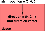
- DirectionalPointSource (Position pointLocation, Direction direction, int initialTissueRegionIndex). This describes a directional point source with a specified orientation e.g.
- normal to tissue surface, starting inside tissue: Position=(0,0,0), Direction=(0,0,1), initialTissueRegionIndex=1.This photon does not go through Fresnel at the tissue surface.
- If Position=(0,0,0) and initialTissueRegionIndex=0, then the photon goes through Fresnel at the tissue surface. This means that some photons, depending on their direction, will be reflected at the tissue surface.
Tissues are comprised of Tissue Regions. Example input files are bundled with the MC1.0 download or can be downloaded from the VTS GUI using the Monte Carlo Solver Panel and clicking "Download Prototype Input Files".
- MultiLayerTissue (IList). MultiLayerTissue is comprised of LayerRegions, for example a homogeneous slab of thickness T would have 3 LayerRegions: 1) air above (layer [start, stop]=[-inf, 0]) , 2) tissue (layer [start, stop]=[0, T]), 3) air below (layer [start, stop]=[T, inf]). The layers should be specified in order from top to bottom and be contiguous, i.e. each layer stop location should agree with the next layer's start location.
- SingleEllipsoidTissue (IList concat EllipsiodRegion) SingleEllipsoidTissue is comprised of LayerRegions concatentated with an EllipsoidRegion. It is assumed that the ellipsoid is contained entirely within a layer region (the ellipsoid cannot span more than 1 layer region). It is also assumed that the refractive index of the ellipsoid is equal to that of the layer is within. Refractive index mismatch between ellipsoid and surrounding tissue layer is planned for a future release of the software.
- LayerRegion (DoubleRange zRange, OpticalProperties ops). This defines a layer infinite in extent along x,y-axes
- EllipsoidRegion (Position center, double radiusX, double radiusY, double radiusZ, OpticalProperties ops).
- CylinderRegion (Position center, double radius, double height, OpticalProperties ops).
- VoxelRegion (DoubleRange x, DoubleRange y, DoubleRange z, OpticalProperties ops).
- Absorbed Energy
- A(ρ,z) [AOfRhoAndZ]: captures deposited energy within volumes designated by cylindrical coordinates [rho,z: mm]. This has been implemented for analog, DAW absorption weighting and unit tested.
- Fluence
- Fluence(ρ,z) [FluenceOfRhoAndZ]: captures fluence within volumes designed by cylindrical coordinates [rho,z: mm]. This has been implemented for analog, DAW absorption weighting and unit tested.
- Reflectance
- Rd [RDiffuse]: captures total diffusely reflected photons (photons that have entered the tissue). This has been implemented for analog, DAW, CAW absorption weighting and unit tested
- R(θ) [ROfAngle]: captures reflected photons as a function of polar angle [theta: radians]. This has been implemented for analog, DAW, CAW absorption weighting and unit tested
- R(ρ,θ) [ROfRhoAndAngle]: captures reflected photons as a function of circular ring detectors on the surface of the tissue [rho: mm] and polar angle [theta: radians]. This has been implemented for analog, DAW, CAW absorption weighting and unit tested.
- R(ρ,ω) [RofRhoAndOmega]: captures reflected photons as a function of circular ring detectors on the surface of the tissue [rho: mm] and temporal frequency [omega: GHz]. This has been implemented for analog, DAW, CAW absorption weighting and unit tested.
- R(ρ,t) [ROfRhoAndTime]: captures reflected photons as a function of circular ring detectors on the surface of the tissue [rho: mm] and time [time: ns]. This has been implemented for analog, DAW, CAW absorption weighting and unit tested.
- R(ρ) [ROfRho]: captures reflected photons as a function of circular ring detectors on the surface of the tissue [rho: mm]. This has been implemented for analog, DAW, CAW absorption weighting and unit tested.
- R(x,y) [ROfXAndY]: captures reflected photons as a function of Cartesian detectors on the surface of the tissue [x,y: mm]. This has been implemented for analog, DAW, CAW absorption weighting and unit tested.**
- Transmittance
- Td [TDiffuse]: captures total diffusely transmitted photons. This has been implemented using analog, DAW, CAW absorption weighting and unit tested.
- T(θ) [TOfAngle]: captures transmitted photons as a function of polar angle [theta: radians]. This has been implemented for analog, DAW, CAW absorption weighting and unit tested.
- T(ρ,θ) [TOfRhoAndAngle]: captures transmitted photons as a function of circular ring detectors on the surface of the tissue [rho: mm] and polar angle [theta: radians]. This has been implemented for analog, DAW, CAW absorption weighting and unit tested.
- T(ρ) [TOfRho]: captures transmitted photons as a functino of polar angle [rho: radians]. This has been implementd for analog, DAW, CAW absorption weighting and unit tested.
- Radiance
- Radiance(ρ,z,θ) [RadianceOfRhoAndZAndAngle]: captures radiance within volumes designated by cylindrical coordinates [rho,z: mm] and polar angle [theta: radians]. This has been implemented for analog, DAW absorption weighting and unit tested.
- Radiance(x,y,z,θ,φ) [RadianceOfXAndYAndZAndThetaAndPhi]: captures radiance within volumes designated by Cartesian coordinates [x,y,z: mm], polar angles [theta: radians], and azimuthal angles [phi: radians]. This has been implemented for analog, DAW absorption weighting and unit tested.
- Momentum Transfer
- MomentumTransfer(ρ,z) [MomentumTransferOfRhoAndZ]
Command line application that allows the user to run a Monte Carlo simulation given a SimulationInput xml file. Use "mc help" for options.
User can specify several MC simulations that execute in parallel with varying optical properties.
Command line post-processor that can read PhotonTerminationDatabase and generate specified detector tally results. Use "mc_post help" for options.
Perturbation Monte Carlo (pMC) capabilities available that will provide detector tally results for perturbed optical properties (mua and mus).
- R(ρ)[pMCROfRho] DAW unit tested
- R(ρ,t) [pMCROfRhoAndTime] DAW unit tested
Reference: Hayakawa et al., "Perturbation Monte Carlo methods to solve inverse photon migration problems in heterogeneous tissues", Optics Letters 26(17), 2001.