Moved to new location https://gitlab.com/pab44/read-rope
This is an open-source hardware project for a device that outputs a certain voltage depending on where the rope/wire is bent.
Hackaday project: https://hackaday.io/project/166557-read-rope-electronic-nerve
Resistive Flex Sensor used: https://www.adafruit.com/product/1070
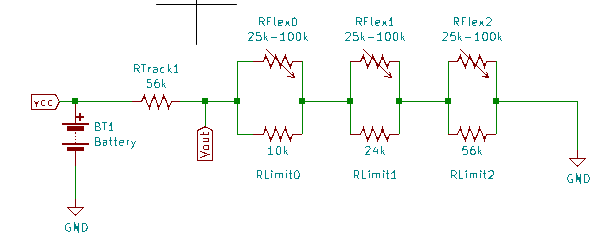
A resistive flex sensor is in parallel with a limiter resistor.
The resistive flex sensor increases in resistance when bent, which increases the voltage at the output.
The limiter resistor in parallel to the resistive flex sensor scales the increase in resistance, which also scales the increase in voltage at the output.
There is a series chain of flexible sections, each containing a parallel combination of a resistive flex sensor and limiter resistor.
Different values for a limiter resistor in each section make for several equivalent resistors in series with each other that contribute different increases in output voltage when bent depending on the limiter resistor value.
If individual limiter resistors resistance value in each section of the chain were set to make the limiter resistor value dependent on the distance from the output node,
then, the increase in output voltage would depend on the distance of a flexible section from the output node thus making output voltage depend on the location of the bend of a flex resistor due to the limiter resistor's value depending on location of the bend.
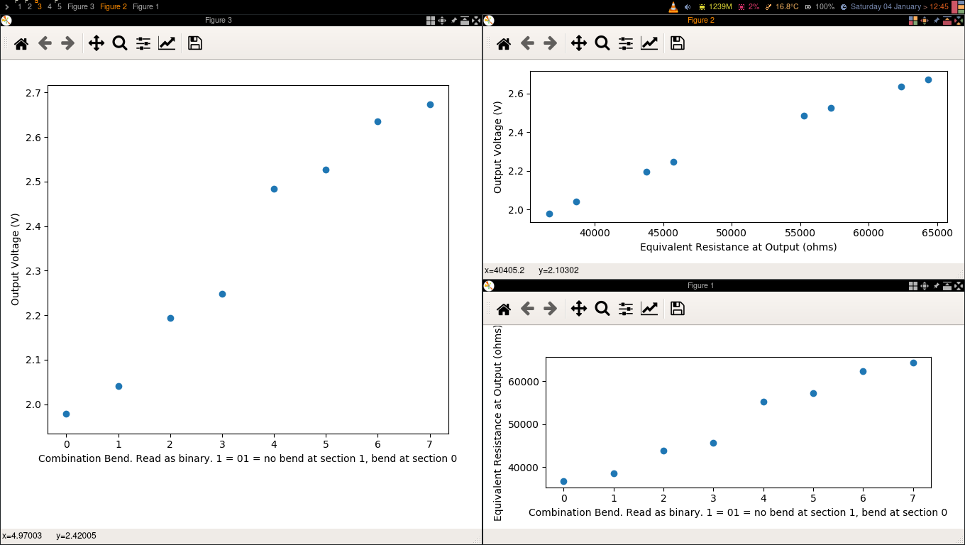
See the diagram/schematic/figure for read rope circuit in read-rope-flex-resistor-diagram.png and the sample results in read-rope-sample-result-4-sections.png.
- Control for disabled
- Virtual Reality/ Augmented Reality (e.g. track precise movement of finger bend, arm bend, leg bend)
- Interactive control for video games
- Interactive control for electronic musical instruments
- Interactive control for training simulation
Have python and ngspice installed.
Run python script read-rope-flex-resistor-circuit-sim.py
python read-rope-flex-resistor-circuit-sim.py
- Look at the Equivalent Resistance at Output vs Combination graph.
- Determine the combination of bends you want to see.
- 0 = no bend, 1 = bend
- combination 1 = 01 = no bend at section 1, bend at section 0
- Look up the equivalent resistant value at output for the combination selected in the Equivalent Output Resistance vs Combination graph.
- Look at the Output Voltage vs Equivalent Resistance at Output graph.
- Look up the output voltage for equivalent resistance in Output Voltage vs Equivalent Resistance at Output graph.
- Look at the Output Voltage vs Equivalent Resistance at Output graph.
- In Output Voltage vs Equivalent Resistance at Output graph, look up the equivalent resistance for output voltage read.
- Look at the Equivalent Resistance at Output vs Combination graph.
- In Equivalent Resistance at Output vs Combination graph, look up the combination number for the equivalent resistant value at output.
- Determine the combination of bends from the combination number.
- 0 = no bend, 1 = bend
- combination 1 = 001 = no bend at section 2,no bend at section 1, bend at section 0
- combination 4 = 100 = bend at section 2, no bend at section 1, no bend at section 0
VCC-Rtrack-Req-GND
Vout = VCC * (Req / (Rtrack + Req))

