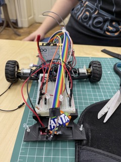
This repository contains the code for an the code for an Arduino line follower with 2 motors built as a project for the Robotics Introduction Course taken in the 3rd year at the Faculty of Mathematics and Informatics of Bucharest.
- Arduino Uno
- Light sensors
- Motor driver
- 2X Motors
- LiPo battery
The robot has to follow a black line agains a white background to complete a circuit. The circuit contains turns and twists that the robot has to follow.
Internally, with the data from the light sensor, a PID controll system is used to decide the speed of each of the 2 motors in order to properly take all the turns.
The PID controll system is composed of 3 elements, the proportional, the derivative and the integral.
- The proportional represents the error scaled by a constant
- The derivative refers to the derivative of the evolution of the error over time. This tells us how fast or slow the error cahnged so that we can accelerate / break accordingly.
- The integral refers to the integral of the evolution of the error over time. This helps us compensate for tiny continous remaing errors if the target is moving. So if we continue missing the target by tiny amounts over time remainng error acumulates using the integral and we get to compensate for it
Both the derivateive and the integral are scaled by constants. Then all 3 values are summed together to give us the speed of each motor. We implemented the derivative and intergral in a more rudimentary manner. The derivateive is the difference between the current and the last error, whyle the integral is the running sum of the errors.
For this project, the integral part of the PID controll system was not needed.
When the arduino starts it firsts performs left to right sweeps while calibrating the sensor. The sweeps ensure that each sensor "sees" both the white background and the black line in order to save the minimum and maximum luminosity values
As previously stated, we used the values from the light sensors as the input of the PID controll systme. The sensors gives values between 0 and 5000 to indicate which beneeth which sensors see the black line. If the first sensor is the only one seeing it, the value returned by the sensor is 0. If the last sensor is the only one seeing the black line, the value returned is 5000.
Since our mottor expects a value between ±255, we scaled the sensor values to ±50. Then, we took these values, applied the PID and used them to correct the speed of each individula motor. A negative error meant that we had to steer to the right and vice versa. To go to the right, we decelerated the left motor by the absolute value of the error and accelerated the other one. We did the opposite to steer to the left.
We found the values of the constants that scaled the P and D by trial and error. We observed that when the factor of P was to small, the robot would refuse to take turns to sharp. So we increesed the facotr of P until the robot would take all the turns. Then if it would start to wobble, we would incread the factor of the derivative. But this would start canceling the effect of the P component. And as such, we would start tweeking the 2 factors until we striked a good balance.