- Abstract
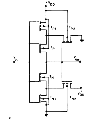
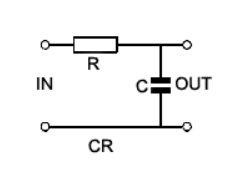
- Reference Circuits and details
- Methodology
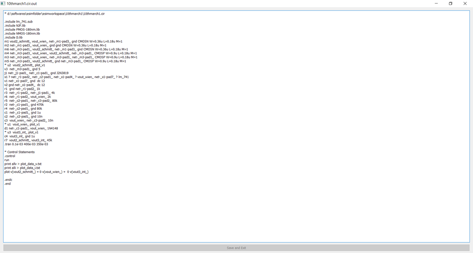
- Software used in implementing the circuit
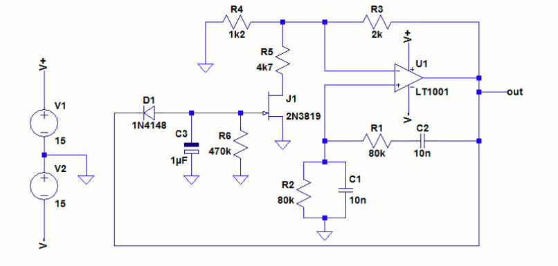
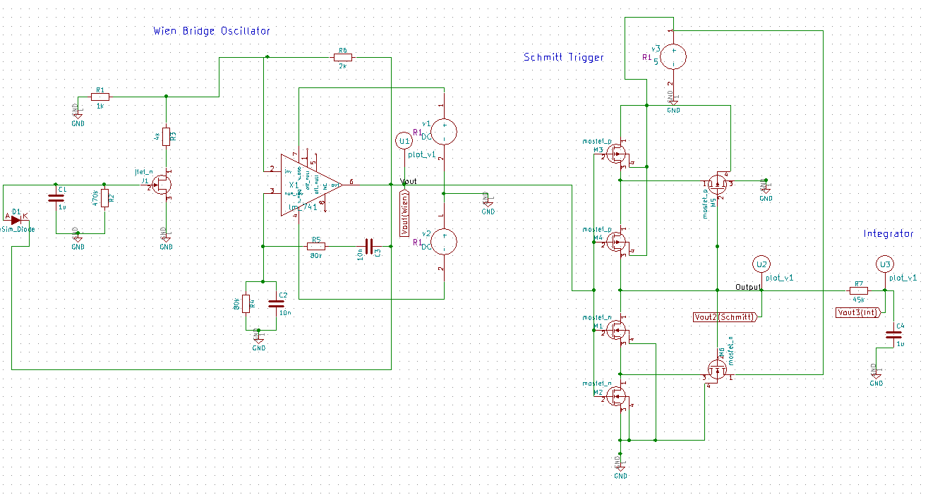
- Implemented Circuit
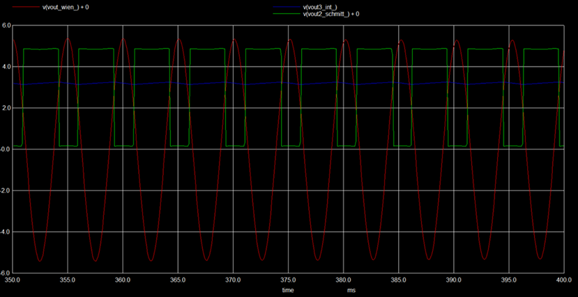
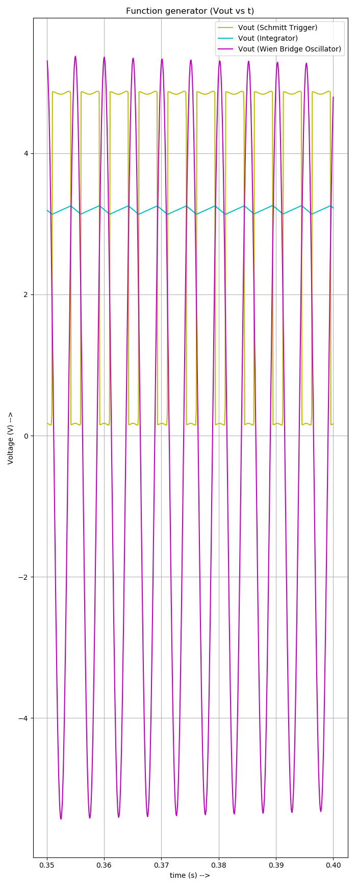
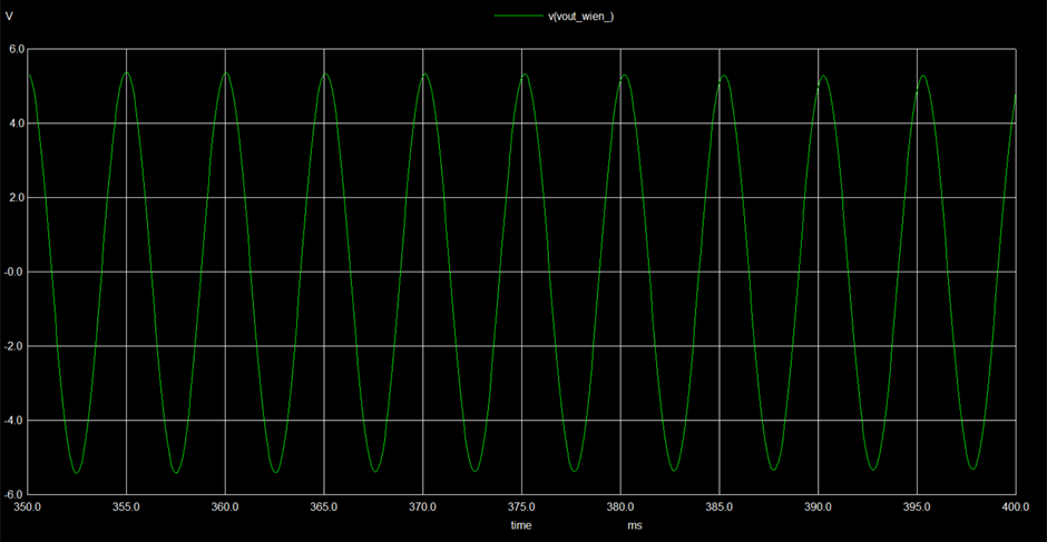
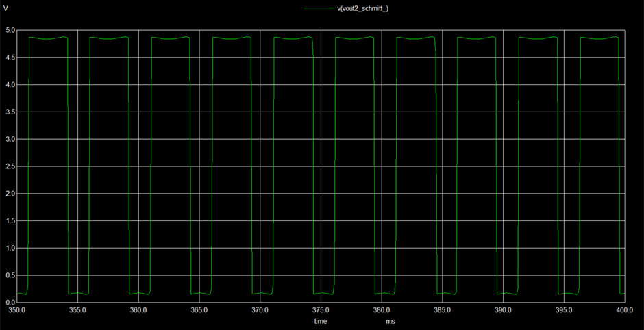
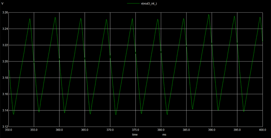
- Implemented Waveforms (Observed Outputs)
Function generators have versatile applications in electronics. In this work, a function generator has been constructed by cascading three well known circuits – The Wien Bridge Oscillator, Schmitt trigger, Integrator. The Wien Bridge Oscillator has been constructed using JFET and Op Amp; Schmitt trigger using CMOS transistors; Integrator using the RC circuitry. The Wien Bridge Oscillator produces a sine wave that acts as an input to the Schmitt trigger circuit which in turn converts it to a square wave. The square wave is further converted to a triangle wave by the integrator. The inital design had descrepancies while simulating and did not give expected results. Modified circuits gave good results. The circuit has applications in signal testing and biomedical instrumentation.
This waveform generator is a combination of the three standard circuits - Wien Bridge Oscillator, Schmitt Trigger and Integrator. The most commonly found, standard electronic circuits were designed differently keeping in mind the efficiency of functioning and advantages to produce a new circuit with versatile applications. The Wien Bridge Oscillator was initially conructed using two JFETs. The Schmitt trigger circuit was constructed using CMOS transistors and an Op Amp RC integrator was used. A lot of descrepancies in the parameters and subsequent waveforms were seen. Owing to this, a new design was adapted using Op Amp and FET (Wien Bridge) and RC Integrator. NMOS and PMOS transistors of 0.180um length, widths of (0.36um and 0.9um respectively) were used. The JFET in the JFET stabilized Wien Bridge circuit is expected to maintain constant, stabilized oscillations. Also, the CMOS Schmitt trigger has advantages like low power consumption, noise immunity, etc. The RC integrator
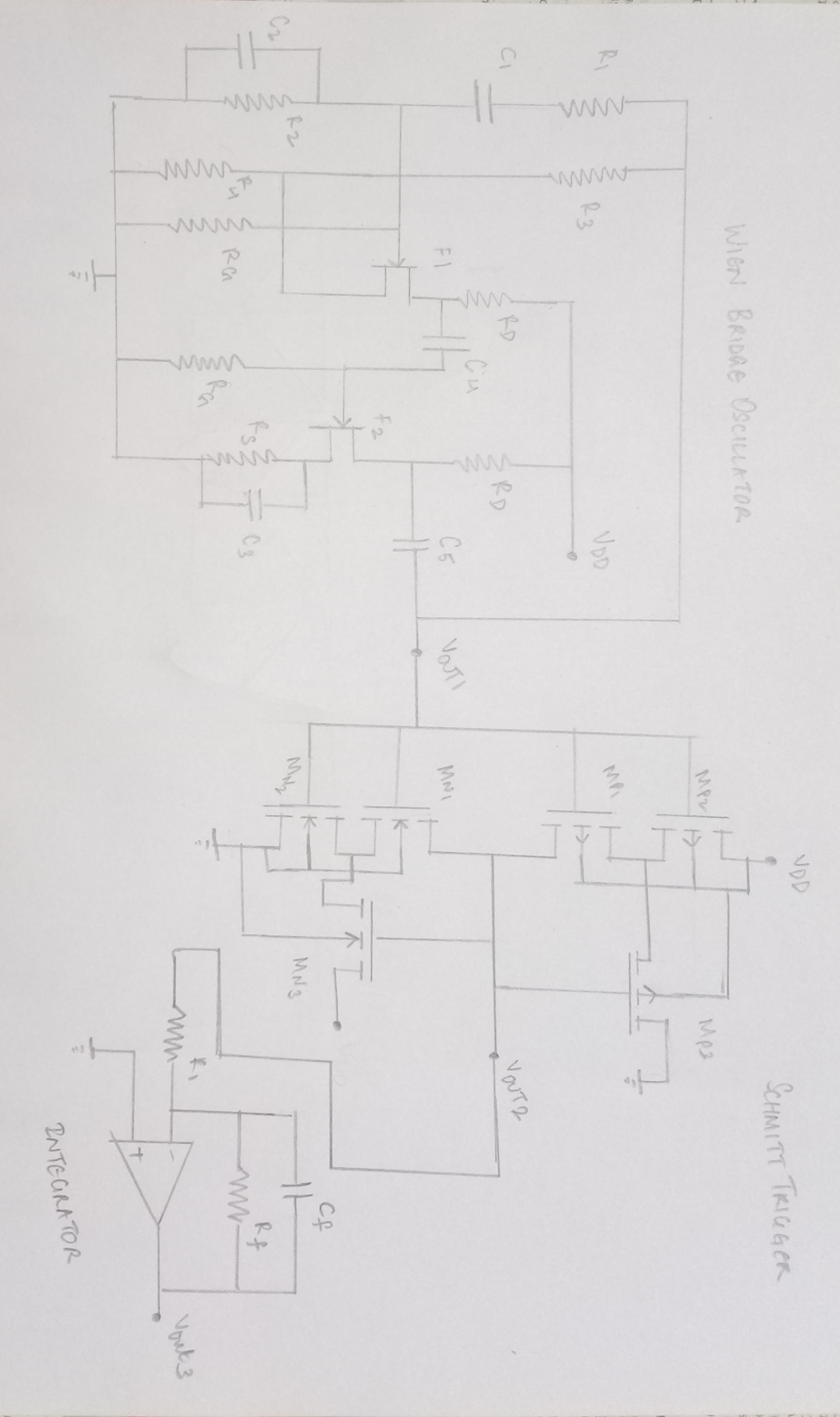
The modified circuit consists of a Wien Bridge Oscillator (JFET and Op Amp), CMOS Schmitt Trigger and RC integrator.
- Design the circuit using eSim
- Convert KiCad to Ngspice
- Simulate
- Perform analysis and trace waveforms
- eSim - It is an Open Source EDA developed by FOSSEE, IIT Bombay. It is used for electronic circuit simulation. It is made by the combination of two software namely NgSpice and KiCAD. For more details refer: https://esim.fossee.in/home
- NgSpice - It is an Open Source Software for Spice Simulations. For more details refer: http://ngspice.sourceforge.net/docs.html
The following are the output waveforms of the implemented circuits.
Function generators are standard circuits in the electronics discipline used to produce different kinds of waveforms (usually sine, square, triangle waves). In an attempt to design a waveform generator, three standard circuits have been employed. Unlike these circuits that function based only on Op Amps, two of them have been designed separately using different components. Wien bridge oscillator has been constructed using an additional JFET and the Schmitt trigger circuit has been constructed using CMOS (PMOS and NMOS) transistors. RC integrator was used to convert square wave into a triangle wave. Each circuit involves separate circuit analysis and formulae to analyze the working. The circuitry and design have been referred from various sources and were cascaded to get a desired output for suitable applications. However, the circuit design proposed in the literature review did not give the expected results and suitable modifications have been carried out. This could be attributed to the internal parameters and time scale variation in subsequent circuits while simulating. Changes in the wave parameters were seen after cascading. However, the modified design produced better results.
It is used to test the working efficieny and outputs of circuits and instruments, to generate waveforms, to drive clock and diode circuits, to study frequency response, etc. Apart from these, waveform/function generators find wide varities of applications in biomedical instrumentation (sensors, pacemaker, ultrasound, etc.)
Ananya N, I M.Sc. Physics (Materials Science), ICT Mumbai
- FOSSEE, IIT Bombay
- Kunal Ghosh, Co-founder, VSD Corp. Pvt. Ltd. - kunalpghosh@gmail.com
- Sumanto Kar, eSim Team, FOSSEE
- Dokic, B. L. (1984, October). CMOS Schmitt triggers. In IEE Proceedings G-Electronic Circuits and Systems (Vol. 131, No. 5, pp. 197-202). IET.
- Filanovsky, I. M., & Baltes, H. (1994). CMOS Schmitt trigger design. IEEE Transactions on Circuits and Systems I: Fundamental Theory and Applications, 41(1), 46-49.
- Integrators. Learnabout-Electronics.Org. Retrieved March 10, 2022, from https://learnabout-electronics.org/ac_theory/filters85.php
- Eevblog.Com. Retrieved March 10, 2022, from https://www.eevblog.com/forum/projects/wien-bridge-oscillator-ltspice-simulation
- Malvino, A. P., & Bates, D. J. (2015). Electronic Principles (8th ed.). McGraw-Hill Education.
- Wein bridge oscillator using JFET. Blogspot.Com. Retrieved March 10, 2022, from http://techpicz.blogspot.com/2012/07/wein-bridge-oscillator-using-jfet.html
- Trigger, C. S. (1975). A Uniquely Versatile Design Component. Fairchild Semiconductor Application Note 140.
- Analysis of a digitally controlled Wien-B. Maximintegrated.Com. Retrieved March 11, 2022, from https://www.maximintegrated.com/en/design/technical-documents/app-notes/3/3846.html