-
-
Notifications
You must be signed in to change notification settings - Fork 11
Home
Meazure is a tool for easily measuring and capturing portions of the screen. Tasks such as measuring the size of a window, capturing an image, determining the color of a pixel, and determining the screen size and resolution can all be easily accomplished using Meazure.
Meazure provides a number of different types of tools for measuring and capturing the screen:
The measurement tools provide a number of key features including:
-
Capture of arbitrary portions of the screen (Rectangle Tool, Circle Tool, and Window Tool)
-
Display of measurements in a variety of units
-
Measurement using the mouse of keyboard including fine adjustment
In addition to the tools listed above, a set of rulers and a grid can be placed on the screen. A magnifier is also provided to help position the measurement tools and to read the color of screen pixels.
Meazure remembers the settings for all measurement tools between runs of the program. In addition, Meazure allows you to save the tool positions to a file. These files, called profiles, can be used to represent an alternate screen size or a required image size.
There are a number of ways to launch the Meazure program.
Start Menu - The most common way to start Meazure is to select the Meazure executable from the Start menu.
Meazure Icon - Double clicking the Meazure desktop icon will launch the program.
Profile File - Double clicking a profile file (a file with an .mea suffix) will launch the Meazure program. Similarly, dragging a profile file and dropping it on the Meazure program icon will run the program and load the profile.
Position Log File - Double clicking a position log file (a file with an .mpl suffix) will launch the Meazure program. Similarly, dragging a position log file and dropping it on the Meazure program icon will run the program and load the positions.
Command Line - Meazure can be launched from the command prompt. The command line syntax is:
meazure [profile]
Extensive online help is available for Meazure. There are a number of ways to access help.
Contents - The table of contents for the online help can be accessed by selecting the Contents item on the Help menu.
F1 Help - Context sensitive help is available by pressing F1 when over the area for which help is needed.
What’s This (Shift F1) - Detailed context sensitive help is available from the >What’s This item on the Help menu or by pressing Shift+F1. When this form of help is selected, the cursor changes to an arrow with a question mark. Move the cursor over the item for which help is needed and click the mouse.
About Meazure - Version and contact information for the Meazure program is available from the About Meazure item on the Help menu. You can also make a financial contribution from the About dialog.
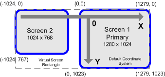
The Meazure program supports systems with multiple display screens. The Windows operating system supports extending the desktop across multiple screens. When the desktop is extended across multiple screens, one screen must be designated as the primary screen. The upper left corner of the primary display screen contains the origin of the overall coordinate system. Windows refers to the virtual screen rectangle as the bounding rectangle that contains all screens. The above figure illustrates a system with two display screens arranged side by side. The screen on the right side is 1280 by 1024 pixels and is designated the primary screen. The screen on the left is 1024 by 768 pixels. Notice that the x-axis coordinates are negative for the left display.
The Meazure program seamlessly measures across multiple screens. Depending on the relative orientation of the screens, the position coordinates may be negative.
The Meazure program always displays the size and resolution information for the screen containing the point being measured (e.g. the screen containing a crosshair that is being dragged). As the measuring point is moved between screens, the screen information is updated to reflect the current screen.
In a multiple display screen environment, each screen has its own resolution. The Meazure program allows the resolution of each screen to be independently calibrated. It is important to calibrate each display screen so that measurements dependent on the screen resolution (e.g. inches) are accurate.
The Meazure program marks the current location of the origin of the coordinate system using the marker shown on the left. The origin is located at the point where the vertical and horizontal lines meet. The horizontal line designates the x-axis with the positive x direction extending to the right from the origin. The vertical line designates the y-axis with the positive direction extending downward from the origin.
Note that if the y-axis is inverted, the origin marker changes its orientation so that the positive y-axis extends upward from the origin as shown in the second figure on the left. If the origin is moved, the marker moves to the new origin. The origin marker can be hidden using the Tools Preferences.


The Windows screen coordinate system has its origin in the upper left corner of the screen with the positive x-axis pointing to the right and the positive y-axis pointing down. This is the default coordinate system used by Meazure. If you prefer using a more familiar coordinate system, select the Invert Y item on the View menu. This will position the origin of the coordinate system in the lower left corner of the screen with the positive x-axis pointing to the right and the positive y-axis pointing up.
If the origin marker is displayed, its orientation reflects the orientation of the y-axis.


The Windows screen coordinate system has its origin in the upper left corner of the screen with the positive x-axis pointing to the right and the positive y-axis pointing down. This is the default coordinate system used by Meazure. If you prefer to have the origin of the coordinate system placed somewhere else on the screen, move Point 1 (cursor, crosshair, or window corner) to the desired position and either select the Set Origin item on the View menu or use the shortcut Ctrl+A. To restore the origin to its default position, select Reset Origin from the View menu.
If the origin marker is displayed, it is positioned at the current location of the origin. When the origin is moved, the origin marker moves to the new location.
The layout of the Meazure program window can be customized to display only the information you require. Each section of the program window can be individually hidden to reduce the visual footprint of the program.
The following items can be selected from the View menu and toggle the display of the respective sections. Meazure remembers which sections have been hidden so that they remain hidden in subsequent runs of the program.
Toolbar - toggles the display of program toolbar.
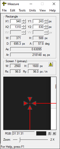
Tool Info - toggles the display of the tool information section.
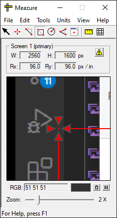
Screen Info - toggles the display of the screen information section.
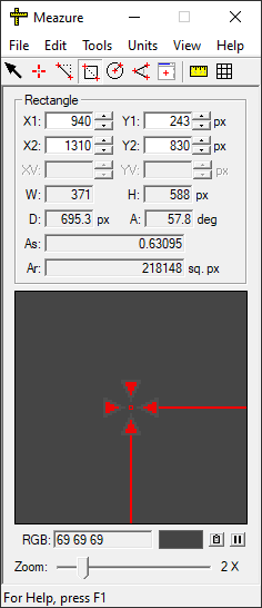
Magnifier - toggles the display of the magnifier window.
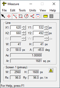
Status Bar - toggles the display of the status bar.
Collapse/Expand - Hides all sections to provide a minimal visual footprint. If hidden, restores the original section layout.

Note that the menu bar cannot be hidden.
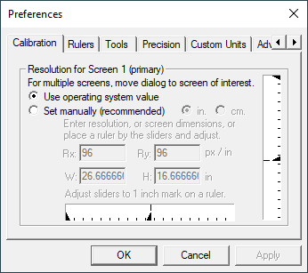
The preferences dialog allows various aspects of the Meazure program to be customized. To display the preferences dialog select the Preferences item from the Edit menu. Preferences are grouped into tabbed sections each focused on one major aspect of the Meazure program.
Calibration - Allows the operating system reported screen resolution to be overridden.
Rulers - Sets the position and appearance of the rulers.
Tools - Set the appearance of measurement tool lines and crosshairs. Also allows the position data window attached to the measurement tools to be turned off.
Precision - Set the number of decimal places to display for each type of measurement in each set of units.
Custom Units - Define a set of custom measurement units.
Advanced - Allows a startup profile to be specified.

To display measurements in units other than pixels, Meazure must convert from pixels using the screen resolution. Meazure assumes that the screen resolution is the operating system default of 96 pixels per inch. However, this value is inaccurate because it does not reflect the physical dimensions of your display screen(s). Meazure allows you manually determine an accurate resolution for each display screen connected to your system. It is highly recommended that you calibrate Meazure the first time you use it and anytime you change a screen’s pixel dimensions (e.g. going from 1024 by 768 to 1280 by 1024 pixels).
To access the resolution calibration panel select the Preferences item on the Edit menu then select the Calibration tab on the Preferences dialog.
The resolution calibration panel displays the calibration state for the screen on which it is displayed. In a multiple screen environment, the calibration panel must be dragged to the screen whose resolution is to be calibrated. The identification of the screen is displayed with the title of the calibration panel frame.
The resolution calibration panel allows you to select whether to use the operating system default for the horizontal and vertical screen resolutions or to use a manual setting of these values. It is highly recommended that you select the manual setting. Before describing the calibration process, the following terms need to be defined:
Screen Resolution - The resolution is the number of pixels per inch or centimeter along the screen. The screen can have a different resolution in the horizontal and vertical directions (e.g. 90 pixels/inch by 96 pixels/inch).
Screen Size - The size of the screen is the number of pixels in the horizontal and vertical directions (e.g. 1280 by 1024 pixels).
Screen Dimensions - The screen dimensions are the length in inches or centimeters in the horizontal and vertical directions (e.g. 13 inches by 10 inches).
There are three methods for manually setting the screen resolution: direct resolution entry, direct dimension entry, or slider calibration. To use any of these methods select Set manually. The resolution can be calibrated using either English or Metric units. Use the inch and centimeter radio buttons to select the units to use for calibration. This selection affects only the calibration units and does not change the measurement units.
Direct resolution entry - If you know the exact screen resolution, use this method to directly enter the horizontal and vertical values using the Rx and Ry text fields. Resolution values must be specified in pixels per inch or pixels per centimeter depending on the calibration units selected.
Direct dimension entry - Using a ruler, you can measure the horizontal and vertical dimensions of the screen. You can then enter these dimension values using the W and H text fields. The dimension values must be specified in inches or centimeters depending on the calibration units selected.
Slider measurement - This method uses a ruler in conjunction with the horizontal and vertical sliders on the panel to set the resolution. Place a ruler on the screen and align it with the zero position on one of the sliders. If resolution calibration is being performed in inches, move the slider until it points to the one inch mark on the ruler. For metric calibration, move the slider until is points to the two centimeter mark on the ruler. Repeat this process for the remaining slider.
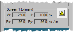
Note that when the operating system resolution is used, a warning button appears on the Screen Information section of the program display. Pressing this button displays the resolution calibration panel.
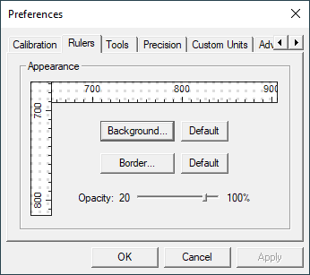
Meazure provides rulers that can be displayed on the screen. The background and border colors and opacity of the rulers can be changed from their defaults. The opacity can be changed from 100% (completely opaque) to 20% (nearly transparent).
To access the ruler preferences panel select the Preferences item on the Edit menu then select the Rulers tab on the Preferences dialog.
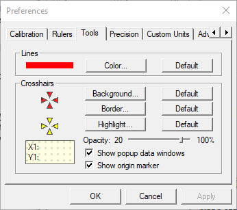
Meazure allows the appearance of the measurement tools to be customized. The following measurement tool characteristics can be customized.
-
Line Color - The color for all lines can be specified using the color dialog displayed when the Color button is pressed. The lines effected include those using in the Line, Rectangle, Circle, Angle and Window tools, as well as those used in the grid. Pressing the Default button restores the original color.
-
Crosshair Background Color - The background color for the crosshairs can be specified using the color dialog displayed when the Background button is pressed. Pressing the Default button restores the original color.
-
Crosshair Border Color - The color for the lines at the edges of the crosshairs can be specified using the color dialog displayed when the Border button is pressed. Pressing the Default button restores the original color.
-
Crosshair Highlight Color - When the pointer is over a crosshair, the highlight color replaces the background color of the crosshair. This highlight color can be specified using the color dialog displayed when the Highlight button is pressed. Pressing the Default button restores the original color.
-
Opacity - The opacity of the crosshairs and data window can be set using the opacity slider. An opacity of 100% means that the crosshairs and data window are completely opaque (i.e. the underlying image does not show through). An opacity of zero results in completely transparent objects.


-
Data Window - Uncheck the box to hide the data windows associated with the measurement tools. The data windows pop up when the pointer moves over a tool’s crosshair.
-
Origin Marker - Uncheck the box to hide the marker that identifies the location of the origin of the coordinate system.
To access the tools preferences panel select the Preferences item on the Edit menu then select the Tools tab on the Preferences dialog.
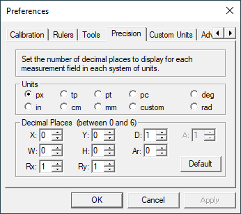
The number of decimal places displayed for each measurement in each set of units can be configured using the Precision panel on the Preferences dialog. From zero to six decimal places may be selected for each measurement type. To change a precision, first select the set of units, then specify the number of decimal places to display for each type of measurement. For example, selecting "in" units and entering three in both the W and H text fields specifies that width and height measurements in inch units should be displayed using three decimal places (e.g. 0.125).
Two types of units can be selected: linear and angular. All positions, lengths and resolutions are specified using linear units (e.g. inches, points). All angles are specified using angular units (e.g. degrees). Selecting a linear set of units, enables the text fields that correspond to linear measurements. Similarly, selecting an angular set of units, enables only those text fields that correspond to angular measurements. Note that custom units are only available for linear measurements. The measurement type text fields are:
-
X, Y - Precisions for position measurements (e.g. X1, Y1)
-
W, H, D - Precisions for length measurements
-
Rx, Ry - Precisions for resolution measurements
-
Ar - Precision for area measurements
-
A - Precision for angle measurements
To restore all precisions for a given set of units back to their original settings, press the Default button.
To access the precision preferences panel select the Preferences item on the Edit menu then select the Precision tab on the Preferences dialog. The precision panel can also be accessed from the Custom Units preferences panel using the Set Display Precision button.
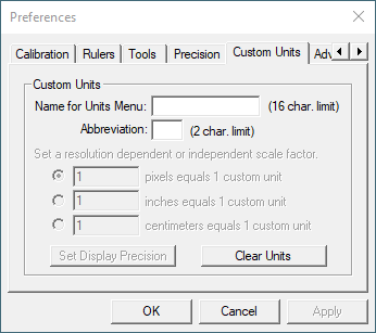
The Meazure program provides a number of measurement units. However, it may be desirable to perform measurements using a set of units that Meazure does not provide. For example, when measuring distances on an online map, it may be useful to use the map’s scale to provide measurements in miles. This can be accomplished using Meazure’s custom units capability.
A custom unit of measure consists of a name for the units and a scale factor. The Meazure program stores these parameters so that the custom units are remembered between runs of the program.
To access the custom units preferences panel, select the Define Custom item from the Units menu. The panel can also be accessed by selecting the Preferences item on the Edit menu then select the Custom Units tab on the Preferences dialog.
The first step in creating custom units is naming the units. Enter the full name for the units in the top text field. This name is used on the Units menu to identify the units. The name can be up to 16 characters. In the Abbreviation text field, enter a two letter abbreviation for the units (e.g. mi for miles). The abbreviation is used to identify the units on the Tool Information and Screen Information sections.
Once a name and abbreviation for the custom units have been entered, the scale factor section of the panel will be enabled. The scale factor is used to convert the custom units to and from a set of units already known to Meazure. The scale factor can be applied directly to pixel measurements or can be applied to a resolution independent set of units such as inches. The scale factor is applied in the following manner depending on the text field selected.
Pixel-based: lengthcustom = lengthpx / scale factorpx per custom
Inch-based: lengthcustom = lengthpx / resolutionpx per in / scale factorin per custom
Centimeter-based: lengthcustom = lengthpx / resolutionpx per in * 2.54cm per in / scale factorcm per custom
Note that accurate measurement using custom units based on inches or centimeters depends on the accuracy of the screen resolution used in the conversion. To ensure accurate measurements, calibrate the screen resolution for your system.
It is likely that you will need to specify the number of decimal places to display for custom units measurements. To set the precision of these measurements, press the Set Display Precision button. This will display the Precision preference panel allowing you to specify the number of decimal places to display for each type of custom units measurement.
Once custom units have been defined, they can be used by selecting name of the units on the Units menu. The name on the Units menu corresponds to the name entered on the Custom Units panel. Once the custom units are selected, the abbreviation for the units is displayed beside each measurement text field on the Tool Information and Screen Information sections.
If custom units have been defined and are no longer needed, they can be deleted by pressing the Clear Units button on the Custom Units preference panel.
For example, an online map uses a scale of 0.5 inch equals 1 mile and we want to perform measurements in miles. Select the Define Custom item on the Units menu. The Custom Units preference panel is displayed. Enter Miles for the name of the units and enter mi for the abbreviation. The scale factor portion of the panel is now enabled. Since the scale factor is based on inches, select the middle radio button. Enter the scale factor 0.5 since half an inch is equal to one mile. Press the display precision button and adjust the number of decimal places to display as needed. Press OK to close the preferences dialog. Finally, select the Miles item that now appears in the Units menu to perform measurements in miles.
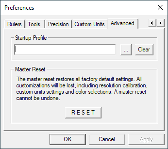
To access the advanced preferences panel select the Preferences item on the Edit menu then select the Advanced tab on the Preferences dialog.
When the Meazure program terminates, it saves its preference settings and the configuration of all tools. Upon startup, Meazure reads these preferences and configurations so that the program appears exactly as it was left. Meazure allows the configuration of the tools to be saved to a file called a profile. You can load a profile anytime while running Meazure. You can also specify a profile to be loaded automatically when Meazure starts up. The Advanced preferences panel provides a text field for you to enter the pathname of a startup profile.
The Meazure program is highly configurable and it is possible to get to a point where it may be desirable to restore the program’s original configuration. The Advanced preferences panel provides a Master Reset button to restore the default program configuration. Pressing the Master Reset button displays a confirmation dialog. If the reset is confirmed, all program settings are returned to their original values including the appearance of the measurement tools. Note that following a reset the position of the measurement tools is not changed but the selected tool is changed to the Cursor tool.
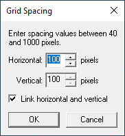
A rectangular grid can be overlaid on the screen to assist in measurement. The size of the grid rectangles can be adjusted using the Screen Grid Spacing dialog. To display the dialog select the Screen Grid Spacing item on the Tools menu.
When the Screen Grid Spacing dialog is displayed, the screen grid will also be displayed regardless of whether it was originally displayed. When the dialog is closed, the screen grid will removed if it was not originally displayed.
The grid spacing is always specified using pixels. The spacing can be set on the horizontal and vertical directions independently or they can be linked to form a square grid by checking the Link box at the bottom of the dialog. To set a spacing either enter a pixel value in one of the text fields or use the up/down buttons next to the text field. The minimum grid spacing is 10 pixels and the maximum spacing is 4000 pixels.
Meazure provides a number of tools for measuring and capturing objects on the screen. Each tool has its own unique characteristics and is designed for different measurement situations. This section provides an overview of the tools and links to the pages providing detailed information on each tool.
Cursor Tool - Tracks the position of the mouse cursor.
Point Tool - Provides a crosshair that can be positioned anywhere on the screen.
Line Tool - Provides two crosshairs connected by a straight line.
Rectangle Tool - Provides two crosshairs connected by a rectangle. Use this tool to measure and capture arbitrary portions of the screen.
Circle Tool - Provides two crosshairs, one at the center of a circle and the other on the circumference of the circle. Use this tool to measure radial distances on online maps. Arbitrary square portions of the screen can be captured using this tool.
Angle Tool - Provides three crosshairs connected by two lines to form a protractor for measuring arbitrary angles on the screen.
Window Tool - Measures the window under the mouse cursor. Use this tool to measure and capture windows and their child windows.
Only one of the above measurement tools can be selected at a time. The following tools can be used in conjunction with the above tools.
Rulers - Places a horizontal and vertical ruler on the edge of the screen.
Screen Grid - Overlays a rectangular grid on the screen.
The Point, Line, Rectangle, Circle, and Angle tools use a crosshair to position the tool and perform measurements. The crosshair consists of four triangular sections pointing to an open center. All measurements are based at the center of the crosshair.
The crosshair can be in one of three visual states: Normal, Located and Find.
Normal - If the mouse is not positioned over the crosshair, it is in the normal state. The crosshair will appear red under the default color scheme.
Located - If the mouse is positioned over the crosshair, it is in the located state. The crosshair will appear yellow under the default color scheme. In addition to a color change, the crosshair will display a data window indicating the current position of the crosshair. A tooltip may also appear indicating which measurement point the crosshair represents.
Find - Sometimes it can be hard to find a tool on the screen. When a new tool is selected, it will flash its crosshairs between the normal and selected states for a few seconds to help you locate it. If you lose a tool after you have selected it, you can cause it to flash again by selecting Find Crosshair on the Tools menu or by using the shortcut Ctrl+F.
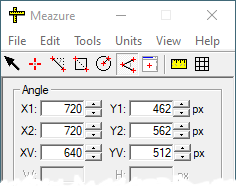
The current position of a crosshair can be read in two places. The first is in the tool information section of the Meazure program window. The second place is the data window associated with the crosshair.


The data window is displayed when the mouse is placed over the crosshair. The Line and Rectangle tools have two crosshairs called Point 1 and Point 2 respectively. The Circle tool has two crosshairs called the Vertex at the center of the circle, and Point 1 on the circumference of the circle. The Angle tool has three crosshairs called Point 1, Point 2, and Vertex. You can determine whether a crosshair is Point 1, 2 or the Vertex either by looking at the data window or the tooltip associated with the crosshair.
Measurements are taken by moving a crosshair to the desired position on the screen. There are four ways to move a crosshair: mouse dragging, text field positioning, fine positioning, and hotkey positioning.
Mouse dragging - The fastest way to position a crosshair is by dragging it using the mouse. Position the mouse over the crosshair so that it is in the located state. Press the left mouse button and drag the crosshair to the desired position. The position of the crosshair will be continuously displayed and the magnifier window will display the area around the crosshair as it is being dragged.

Text field positioning - The crosshair can be positioned by entering a position in the text fields of tool information section of the program. After typing in the position, press Enter to move the crosshair to the new position.
Fine positioning - To move the crosshair in single pixel increments use the up/down buttons located next to each position text field. The keyboard can also be used to move the crosshairs. Pressing Ctrl+1, Ctrl+2 and/or Ctrl+3 along with an arrow key will move the currently selected tool crosshair a single pixel. The number specifies the crosshair to move. Multiple crosshairs can be moved at the same time by pressing multiple numbers. For example, pressing Ctrl+1+2 and the Up arrow moves the Point 1 and Point 2 crosshairs up one pixel.
Hotkey positioning - The crosshair can be moved to the current location of the mouse pointer using Ctrl+Shift+1, Ctrl+Shift+2 or Ctrl+Shift+3. The number specifies which crosshair to move in the currently selected tool. For example, if the Line tool is selected, pressing Ctrl+Shift+2 moves the line’s second position crosshair to the current mouse location. If the Angle tool is selected, pressing Ctrl+Shift+3 moves the vertex of the angle to the current mouse location.
The display of the crosshair can be toggled either by selecting the Hide Crosshairs item on the Tools menu or by pressing Ctrl+B.
The colors, opacity and other characteristics of the crosshair and data window can be changed using the Tools panel on the Preferences dialog.


The cursor measurement tool allows you to track the position of the mouse cursor. Both the data window attached to the cursor and Meazure’s tool information section will display the position of the cursor. Note that the position of the cursor cannot be changed using the position text fields. The magnifier window will show the area around the cursor as well as the color of the pixel currently under the cursor hotspot. The Cursor tool does not effect normal operation of the mouse cursor.
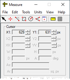
To select the Cursor tool choose the Cursor item on the Tools menu or click on the Cursor tool icon on the toolbar.
The point measurement tool allows you to position a crosshair anywhere on the screen and measure the position. Both the data window attached to the crosshair and Meazure’s tool information section will display the position of the crosshair. The magnifier window will show the area around the crosshair as well as the color of the pixel at the center of the crosshair.
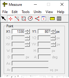
The mouse or keyboard can be used to position the crosshair. Fine adjustment can be made with the up/down buttons adjacent to the position text fields or pressing Ctrl+1 and an arrow key. When using the mouse to drag the crosshair, the Shift key can be used to lock the motion of the crosshair to the horizontal or vertical directions. Press Ctrl+Shift+1 to position the crosshair at the current location of the mouse pointer.
To select the Point tool choose the Point item on the Tools menu or click on the Point tool icon on the toolbar.


The line measurement tool allows you to position two crosshairs anywhere on the screen and measure the positions, distance and other information for the line connecting them. Both the data window attached to the crosshairs and Meazure’s tool information section will display the measurement information. The magnifier window will show the area around the crosshair that is being moved as well as the color of the pixel at the center of the crosshair.
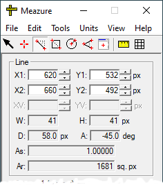
The tool information section displays the following measurements for the Line tool:
-
X1, Y1 - The position of the Point 1 crosshair
-
X2, Y2 - The position of the Point 2 crosshair
-
W, H - The width and height of the bounding rectangle for the line.
W = |X2 - X1| + 1,H = |Y2 - Y1| + 1 -
D - The length of the line connecting the two crosshairs.
D = sqrt(W2 + H2)


-
A - The angle of the line relative to the x-axis. Using the default coordinate system, positive angles are measured clockwise from the positive x-axis to the line from Point 1 to Point 2
-
As - The aspect ratio of the bounding rectangle for the line.
As = W / H -
Ar - The area of the bounding rectangle for the line.
Ar = W * H
Note that the calculation of W, H, D and Ar is always performed in pixel units and the result is converted to the currently selected display units.
The mouse or keyboard can be used to position the crosshairs. Fine adjustment can be made with the up/down buttons adjacent to the position text fields or pressing the Ctrl+1 and/or Ctrl+2 and an arrow key. When using the mouse to drag a crosshair, the Shift key can be used to lock the line to the horizontal or vertical direction. The entire line can be moved by pressing the Ctrl key while dragging one of the crosshairs. Press Ctrl+Shift+1 to position the Point 1 crosshair at the current location of the mouse pointer. Similarly, use Ctrl+Shift+2 to position the Point 2 crosshair at the mouse pointer location.
To select the Line tool choose the Line item on the Tools menu or click on the Line tool icon on the toolbar.
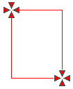

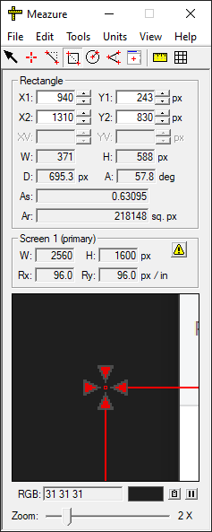
The rectangle measurement tool allows you to position two crosshairs anywhere on the screen and measure the enclosing rectangle. In addition, the screen area bounded the rectangle can be captured to the clipboard. Both the data window attached to the crosshairs and Meazure’s tool information section will display the rectangle measurement information. The magnifier window will show the area around the crosshair that is being moved as well as the color of the pixel at the center of the crosshair.
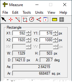
The tool information section displays the following measurements for the Rectangle tool:
-
X1, Y1 - The position of the Point 1 crosshair
-
X2, Y2 - The position of the Point 2 crosshair
-
W, H - The width and height of the rectangle.
W = |X2 - X1| + 1,H = |Y2 - Y1| + 1 -
D - The length of the diagonal.
D = sqrt(W2 + H2)


-
A - The angle of the diagonal relative to the x-axis. Using the default coordinate system, positive angles are measured clockwise from the positive x-axis to the line from Point 1 to Point 2
-
As - The aspect ratio of the rectangle.
As = W / H -
Ar - The area of the rectangle.
Ar = W * H
Note that the calculation of W, H, D and Ar is always performed in pixel units and the result is converted to the currently selected display units.
To capture the screen area bounded by the rectangle to the clipboard, select the Copy Region item from the Edit menu or press Ctrl+R.
The mouse or keyboard can be used to position the crosshairs. Fine adjustment can be made with the up/down buttons adjacent to the position text fields or by pressing Ctrl+1 and/or Ctrl+2 and an arrow key. When using the mouse to drag a crosshair, the Shift key can be used to lock the motion to the horizontal or vertical direction. The entire rectangle can be moved by pressing the Ctrl key while dragging one of the crosshairs. Press Ctrl+Shift+1 to position the Point 1 crosshair at the current location of the mouse pointer. Similarly, use Ctrl+Shift+2 to position the Point 2 crosshair at the mouse pointer location.
To select the Rectangle tool choose the Rectangle item on the Tools menu or click on the Rectangle tool icon on the toolbar.
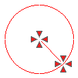

The circle measurement tool allows you to position two crosshairs, one marking the center of a circle and the other marking a point on the circumference of the circle. This tool is ideal for use with online maps. In addition, the screen area contained in the square bounding the circle can be captured to the clipboard. Both the data window attached to the crosshairs and Meazure’s tool information section will display the measurement information. The magnifier window will show the area around the crosshair that is being moved as well as the color of the pixel at the center of the crosshair.
image::images/CircleDisplay.png" width="236" height="270" border="0" title="Circle Tool Display" alt="Circle tool display">
The tool information section displays the following measurements for the Circle tool:
-
XV, YV - The position of the crosshair at the center of the circle
-
X1, Y1 - The position of the Point 1 crosshair on the circumference of the circle
-
W, H - The width and height of the bounding square.
W = H = 2 * D -
D - The radius of the circle.
D = W / 2


-
A - The angle of the radius relative to the x-axis. Using the default coordinate system, positive angles are measured clockwise from the positive x-axis to the line from center of the circle to Point 1 on the circumference
-
Ar - The area of the circle.
Ar = pi * D2
Note that the calculation of W, H, D and Ar is always performed in pixel units and the result is converted to the currently selected display units.
To capture the screen area bounded by the circle to the clipboard, select the Copy Region item from the Edit menu or press Ctrl+R.
The mouse or keyboard can be used to position the crosshairs. Fine adjustment can be made with the up/down buttons adjacent to the position text fields or pressing Ctrl+1 and/or Ctrl+3 and an arrow key. When using the mouse to drag a crosshair, the Shift key can be used to lock the motion to the horizontal or vertical direction. The entire rectangle can be moved by pressing the Ctrl key while dragging one of the crosshairs. Press Ctrl+Shift+1 to position the Point 1 crosshair at the current location of the mouse pointer. Use Ctrl+Shift+3 to position the center crosshair at the mouse pointer location.
To select the Circle tool choose the Circle item on the Tools menu or click on the Circle tool icon on the toolbar.
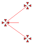

The angle measurement tool provides an protractor for measuring arbitrary angles on the screen. The tool provides three crosshairs that can be positioned anywhere on the screen. One crosshair is located at the vertex of the angle and the other two crosshairs define the angle. The measured angle is on the same side as the angle bisector line. Both the data window attached to the crosshairs and Meazure’s tool information section will display the angle measurement information. The magnifier window will show the area around the crosshair that is being moved as well as the color of the pixel at the center of the crosshair.
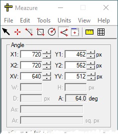
The tool information section displays the following measurements for the Angle tool:
-
X1, Y1 - The position of the Point 1 crosshair
-
X2, Y2 - The position of the Point 2 crosshair
-
XV, YV - The position of the angle vertex crosshair


-
A - The angle formed by the lines from the vertex to Point 1 and Point 2. The angle is measured on the side of the tool that contains the angle bisector line. Using the default coordinate system, positive angles are measured clockwise from the Point 1 line to the Point 2 line
The mouse or keyboard can be used to position the crosshairs. Fine adjustment can be made with the up/down buttons adjacent to the position text fields or by pressing Ctrl+1, Ctrl+2 and/or Ctrl+3 and an arrow key. When using the mouse to drag a crosshair, the Shift key can be used to lock the motion to the horizontal or vertical direction. The entire rectangle can be moved by pressing the Ctrl key while dragging one of the crosshairs. Press Ctrl+Shift+1 to position the Point 1 crosshair at the current location of the mouse pointer. Similarly, use Ctrl+Shift+2 to position the Point 2 angle crosshair at the mouse pointer location. Press Ctrl+Shift+3 to position the angle vertex crosshair at the mouse pointer location.
To select the Angle tool choose the Angle item on the Tools menu or click on the Angle tool icon on the toolbar.
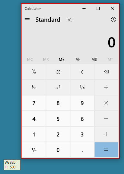
The window measurement tool allows you to measure the size of any window on the screen including its child windows. In addition, the window contents can be captured to the clipboard. The window being measured is identified by a red rectangular border. Both the data window attached to the window border and Meazure’s <<topic_tool_information_section, tool information section> will display the window measurement information. Note that the position of the Window tool cannot be changed using the position text fields.
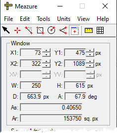
The tool information section displays the following measurements for the Window tool:
-
X1, Y1 - The position of the upper left corner of the window
-
X2, Y2 - The position of the lower right corner of the window
-
W, H - The width and height of the window.
W = |X2 - X1| + 1,H = |Y2 - Y1| + 1 -
D - The length of the window diagonal.
D = sqrt(W2 + H2)


-
A - The angle of the diagonal relative to the x-axis. Using the default coordinate system, positive angles are measured clockwise from the positive x-axis
-
As - The aspect ratio of the window.
As = W / H -
Ar - The area of the window.
Ar = W * H
Note that the calculation of W, H, D and Ar is always performed in pixel units and the result is converted to the currently selected display units.
To capture the window contents to the clipboard, select the Copy Region item from the Edit menu or press Ctrl+R.
To select the Window tool choose the Window item on the Tools menu or click on the Window tool icon on the toolbar.
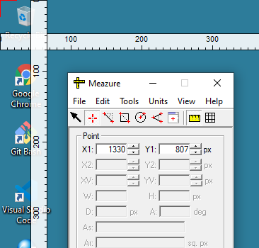
To assist in measuring items on the screen, a set of horizontal and vertical rulers can be displayed. By default, the rulers will be displayed on the top and left edges of each display screen. The position of the rulers can be changed by dragging them across the screen using the mouse. To aid in measurement, the rulers can be made partially transparent using the ruler preferences.
Rulers can be used in conjunction with any other measurement tool including the screen grid. The rulers provide indicators that show the position of the current measurement tool. For example, when the Cursor tool is selected, the ruler indicator will show the current position of the mouse cursor.
To select the rulers choose the Rulers item on the Tools menu or click on the rulers icon on the toolbar.
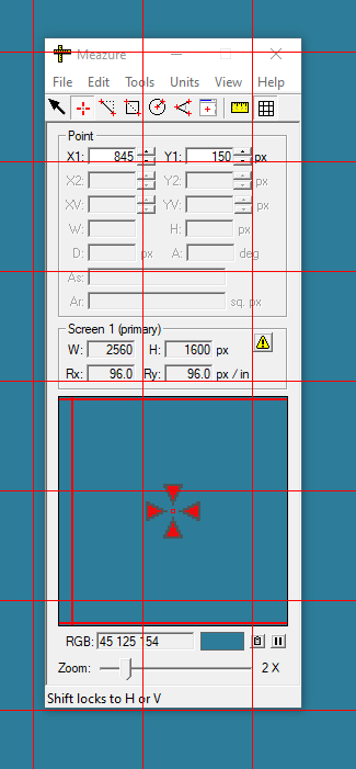
A rectangular grid can be overlaid on the screen to assist in measuring. The grid will not effect mouse cursor interaction with other windows. The size of the grid rectangles can be adjusted by selecting the Screen Grid Spacing item from the *Tools menu.
To select the screen grid choose the Screen Grid item on the Tools menu or click on the screen grid icon on the toolbar.
Meazure offers a variety of units in which to display linear and angular measurements each selected using the Units menu. The linear units are used to measure positions, lengths and resolutions.
-
Pixels - Picture elements are the fundamental unit of measure available from Meazure.
-
Twips - These units are typically used by programs such as Visual Basic when designing screen dialogs. One twip is equal to 1/1440 of an inch or 1/20 of a point.
-
Points - The point is most commonly used in typography to measure the height of characters in a font. One point is equal to 1/72 of an inch.
-
Picas - One pica is equal to 12 points. Therefore, one pica is equal to 1/6 of an inch.
-
Inches - Standard English unit of measure.
-
Centimeters - Standard metric unit of measure. There are 2.54 centimeters to one inch.
-
Millimeters - Standard metric unit of measure. There are 25.4 millimeters to one inch.
Angles are measured using one of the following units.
-
Degrees - Measures between 0 and 360 degrees for a full circle.
-
Radians - Measures between 0 and 2 * pi radians for a full circle.
All linear units except pixels require Meazure to convert from pixels to the desired units using the screen resolution (dots per inch). For the conversion to be correct, the screen resolution values must be correct. By default, Meazure uses the screen resolution values reported by the Windows operating system. These values are not accurate. You should determine the true screen resolution using the Resolution Calibration dialog. When you first select units that requires the use of the screen resolution, a dialog will be displayed urging you to calibrate Meazure. To learn more about the screen resolution see the Resolution Calibration online help.
A custom set of linear measurement units can be defined using the Custom Units preferences. Once a set of custom units has been defined, it is displayed on and can be selected using the Units menu.
Position logging is a feature of the Meazure program that allows the recording of successive tool positions. For example, the Cursor tool or Point tool can be used to digitize positions along a path. The recorded positions can be played back, saved to a file and subsequently reloaded.
The position of the current measurement tool is saved either by selecting the Record Position item from the Edit menu, by pressing Ctrl+P, or by using the Add button on the position management dialog. A number of supporting items are recorded along with the current tool and its position. These items include a time stamp, the current screen size and resolution, the location of the coordinate system origin, and the current units. Recorded positions can be managed or saved to a file.
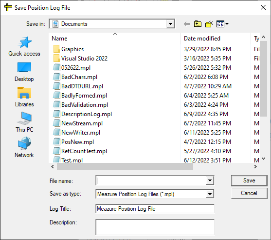
Once one or more positions have been recorded they can be saved to a position log file. To save the recorded positions select either the Save Positions or Save Positions As item from the File menu. In addition, the positions can be saved using the appropriate buttons on the position management dialog. The file save dialog is the standard Windows save dialog with the addition of a text field for entering an optional description of the position log. The description, if provided, is saved in the log file.
Positions are saved to an XML file with a .mpl file extension. The format of the file is described by the Position Log file DTD located at https://www.cthing.com/dtd/PositionLog1.dtd. A copy of the DTD is installed with the Meazure program in the dtd folder (typically C:\Program Files\C Thing Software\Meazure\dtd).
A position log file is loaded by selecting the Load Positions item from the File menu or by using the Load button on the position management dialog. Once a position log file has been loaded, the position management dialog is displayed to allow playback of the positions.
A position log file differs from a profile file in the following way. A profile file is designed to save a complete snapshot of the Meazure program. That is, all tool positions, appearance settings, calibrations, and all other preferences are saved in a profile file. In contrast, a position log file records the position of the current measurement tool at a point in time and includes only those supporting items necessary to replay the positions.
Recorded positions can be deleted selectively using the position management dialog, or can be completely deleted using either the management dialog or the Delete Positions item on the Edit menu.
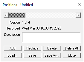
The position management dialog provides a one stop shop for recording, editing, saving, loading and playing back measurement tool positions. The position management dialog is non-modal and can be accessed from the Manage Positions item on the Edit menu. In addition, the dialog is displayed whenever a position log file is loaded.
At the top of the position management dialog is the position playback slider. Once positions have been recorded or loaded, the slider can be used to step through each position. The information about each position is displayed immediately below the playback slider. This information includes the time stamp and description associated with the position.
At the bottom of the dialog is a set of buttons that provide complete control over managing measurement tool positions.
-
Add - Records the current measurement tool position.
-
Replace - Replaces the position selected by the playback slider with the current measurement tool position.
-
Delete - Deletes the position selected by the playback slider.
-
Delete All - Deletes all recorded positions.
-
Load - Loads a position log file thereby replacing the currently recorded positions, if any.
-
Save - Saves the currently recorded positions to a position log file.
-
Save As - Saves the currently recorded positions to a position log file.
-
Close - Dismisses the dialog.
Meazure allows you to save the configuration of all measurement tools to a disk file called a profile. The following information is saved in a profile:
-
The currently selected measurement tool.
-
The positions of the Point, Line, Rectangle, Circle, and Angle measurement tools.
-
The current measurement units.
-
The position of the coordinate system origin and whether the direction of the y-axis is inverted.
-
The positions of the rulers and whether they are displayed.
-
The screen grid spacing and whether the grid is displayed.
To save a profile, select the Save Profile item on the File menu or use the Ctrl+S shortcut. To load a profile, select the Load Profile item on the File menu or use the Ctrl+O shortcut. A profile can be automatically loaded at startup by specifying the file pathname on the Advanced Preferences panel.
Profile files can be saved anywhere on disk. The files are identified by the .mea extension. Double clicking on a profile file will run the Meazure program and load the specified profile. Similarly, dragging a profile file and dropping it on the Meazure program icon will run the program and load the profile.
A number of sample profiles are provided with Meazure.
A profile file differs from a position log file in the following way. A profile file is designed to save a complete snapshot of the Meazure program. That is, all tool positions, appearance settings, calibrations, and all other preferences are saved in a profile file. In contrast, a position log file records the position of the current measurement tool at a point in time and includes only those supporting items necessary to replay the positions.
Meazure provides a number of sample profiles. Each profile selects the Rectangle measurement tool in pixel units and sets it to correspond to a standard screen size (e.g. 1280 x 1024, NTSC). One use of the sample profiles is to check that a page layout will fit a particular screen size.
The sample profiles are located in the Profiles folder where Meazure has been installed (typically C:\Program Files\C Thing Software\Meazure\Profiles). This is the default folder for saving and loading profiles.
The Meazure program window is divided into six sections: menu bar, toolbar, tool information, screen information, magnifier, and status bar.
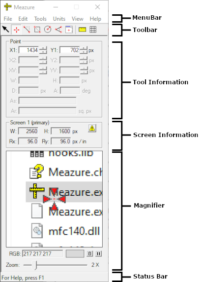
Menu Bar - All program functionality is accessible through the menu bar.
Toolbar - The toolbar provides quick selection of measurement tools.
Tool Information - Measurement information for the currently selected tool is displayed in this section.
Screen Information - The screen size and resolution are displayed in this section.
Magnifier - This section provides a magnified view of the area around the current measurement tool. In addition, this section provides the color of the pixel at the point of measurement.
Status Bar - Program runtime information is displayed in this section.
Meazure allows you to customize its layout. Any of the above sections can be hidden with the exception of the menu bar.
Load Positions… |
Ctrl+O |
Loads the position log file specified by the file selection dialog. |
Save Positions |
Ctrl+S |
Save the current recorded positions to the position log file. |
Save Positions As… |
Save the current recorded positions to the position log file specified by the file selection dialog. |
|
Load Profile… |
Loads the profile specified by the file selection dialog. |
|
Save Profile… |
Saves the current tool configuration to the profile specified by the file selection dialog. |
|
Exit |
Terminates the program. |
Cut |
Ctrl+X |
Cuts the selected text field contents to the clipboard. |
Copy |
Ctrl+C |
Copies the selected text field contents to the clipboard. |
Copy Region |
Ctrl+R |
If the Rectangle, Circle, or Window tool is selected, this menu item copies to the clipboard the contents of the screen bounded by the tool. |
Paste |
Ctrl+V |
Pastes the contents of the clipboard into the text field that has the focus. |
Delete |
Deletes the selected text field contents. |
|
Record Position |
Ctrl+P |
Records the position of the current measurement tool. |
Manage Positions |
Displays the position management dialog. |
|
Delete Positions |
Deletes all recorded positions. |
|
Preferences… |
Displays the preferences dialog. |
Selects a measurement tool. Only one of these measurement tools can be selected at a time. |
||
Rulers |
Displays the rulers on the screen. Rulers can be displayed in conjunction with any of the other measurement tools. |
|
Screen Grid |
Overlays a rectangular grid on the screen. The grid can be used in conjunction with any of the other measurement tools. |
|
Screen Grid Spacing… |
Displays a dialog that allows you to adjust the spacing of the screen grid. |
|
Hide Crosshairs |
Ctrl+B |
Toggles the display of the current measurement tool’s crosshairs. |
Find Crosshairs |
Ctrl+F |
As an aid in finding lost tool crosshairs, selecting this menu item will cause the crosshairs to flash. |
Pixels |
Selects display of linear measurements in pixels |
Twips |
Selects display of linear measurements in twips |
Points |
Selects display of linear measurements in points |
Picas |
Selects display of linear measurements in picas |
Inches |
Selects display of linear measurements in inches |
Centimeters |
Selects display of linear measurements in centimeters |
Millimeters |
Selects display of linear measurements in millimeters |
[custom] |
Selects display of linear measurements in user defined units |
Define Custom… |
Allows user to define custom linear measurement units |
Degrees |
Selects display of angular measurements in degrees |
Radians |
Selects display of angular measurements in radians |
Collapse/Expand |
Ctrl+H |
Hides all sections to provide a minimal visual footprint. If hidden, restores the original section layout. |
Toolbar + Tool Info + Screen Info + Magnifier + Status Bar |
Hides or displays the specified program section. |
|
Magnifier Grid |
Toggles the display of the grid on the magnifier window. Note that the magnifier grid is only shown at 4X magnification and above. |
|
Zoom In |
Ctrl++ |
Increases the magnifier zoom. |
Zoom Out |
Ctrl+- |
Decreases the magnifier zoom. |
Freeze Magnifier |
Ctrl+M |
Freezes the magnifier window so that its contents do not change. |
Color Format |
Selects the display format for the pixel color value. |
|
Invert Y |
Moves the origin and inverts the direction of the y-axis so that the positive y direction is up from the lower left of the screen. |
|
Supplemental Angle |
Changes the angle display from showing the included angle to showing the supplemental angle. The supplemental angle added to the included angle equals 180 degrees. |
|
Set Origin |
Ctrl+A |
Sets the origin of the measurement coordinate system to the position of the current measurement tool. |
Reset Origin |
Resets the origin of the measurement coordinate system to its default location (top left corner of the screen). |
|
Always Visible |
Ensures that the Meazure program window and its tools cannot be obscured by other windows. |
Contents |
Displays the online help table of contents. |
|
What’s This? |
Shift+F1 |
Displays a context help cursor that allows you to obtain help on any area of the program by clicking on that area. |
Meazure Releases |
Opens a web browser to the site where the latest version of Meazure can be downloaded. |
|
Report an Issue |
Opens a web browser to report bugs or request new features. |
|
About Meazure |
Displays a dialog with important information about Meazure. |
The Meazure toolbar offers a quick way to select a measurement tool.
Cursor Tool - Tracks the position of the mouse cursor.
Point Tool - Provides a crosshair that can be positioned anywhere on the screen.
Line Tool - Provides two crosshairs connected by a straight line.
Rectangle Tool - Provides two crosshairs connected by a rectangle. Use this tool to measure and capture arbitrary portions of the screen.
Circle Tool - Provides two crosshairs, one at the center of a circle and the other on the circumference of the circle. Use this tool to measure radial distances on online maps. Arbitrary square portions of the screen can be captured using this tool.
Angle Tool - Provides three crosshairs connected by two lines to form a protractor for measuring arbitrary angles on the screen.
Window Tool - Measures the window under the mouse cursor. Use this tool to measure and capture windows and their child windows.
Only one of the above measurement tools can be selected at a time. The following tools can be used in conjunction with the above tools.
Rulers - Places a horizontal and vertical ruler on the edge of the screen.
Screen Grid - Overlays a rectangular grid on the screen.
All toolbar items on the toolbar can also be selected using the Tools menu.
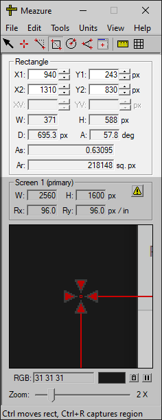
Measurement information for the currently selected tool is displayed in the Tool Information section. The name of the current measurement tool is displayed at the top of the section. Depending on the tool selected, various text fields in this section will be enabled for input and display. The exact meaning of each text field is dependent on the selected measurement tool.
The position text fields (i.e. X1/Y1, X2/Y2, XV/YV) provide a pair of up/down buttons that allow fine adjustment of the tool position.
X1, Y1 - Position 1
X2, Y2 - Position 2
XV, YV - Angle vertex position or circle center position
W, H - Width and height
D - Distance or radius
A - Angle
As - Aspect ratio
Ar - Area
Note that the calculation of W, H, D and Ar is always performed in pixel units and the result is converted to the currently selected display units.
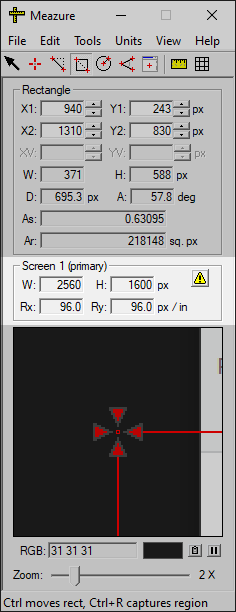
The size and resolution of the screen is displayed in the Screen Information section. In a multiple screen environment, the information displayed is for the screen containing the measurement tool crosshair or appropriate measurement mechanism. The screen to which the displayed information pertains is identified in the section’s frame.
W, H - Width and height of the screen
Rx, Ry - Horizontal and vertical resolution of the screen
By default the screen resolution shown is the default for the operating system (96 DPI). In addition to displaying the screen resolution, Meazure uses the values to convert measurements from pixels to other units. The operating system values for screen resolution are inaccurate and should overridden using the Calibration tab on the Preferences dialog.

Note that when the operating system resolution is used for any screen, a warning button appears in the upper right corner of the section. Pressing this button displays the resolution calibration panel.
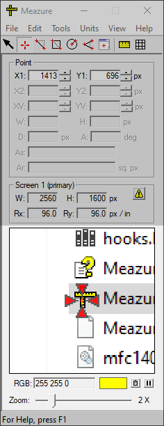
The magnifier provides a view of the area around a measurement tool. In addition, the color of the pixel at the center of the view is shown. There are three parts to the magnifier: the magnifier window, the color display, and the zoom and freeze controls.
The magnifier window displays the area around the current measurement tool (e.g. cursor, crosshair) magnified by the current zoom factor. When the Cursor tool or Window tool is selected, the center of the magnifier is outlined by a red square that corresponds to the hotspot of the cursor. When a tool is selected that uses a crosshair, the red outline at the center of the magnifier corresponds to the center of the crosshair that is being positioned.
A grid is overlaid on the magnifier window when the zoom factor is 4X or greater. To turn off this grid select the Magnifier Grid item on the View menu.
The color of the pixel at the center of the magnifier window is shown below the magnifier window. The color is shown in the swatch at the right of the section and the color value is displayed on the left. The color value is reported in one of the following formats depending on the selection made on the Color Format submenu on the View menu.
Color Space Formats
-
RGB - The color is displayed as separate red, green, and blue components each as a value between 0 and 255 inclusive.
-
#RRGGBB - The color is displayed as a single six digit hexadecimal number where the first two digits are the red component, the next two digits are the green component and the last two digits are the blue component. The value of each component is between 0 and 0xFF inclusive.
-
CMY - The color is displayed as separate cyan, magenta, and yellow components each as a value between 0 and 255 inclusive.
-
CMYK - The color is displayed as separate cyan, magenta, yellow, and black components. The value of each component is between 0 and 255 inclusive.
-
HSL - The color is displayed as hue, saturation, and lightness values. The hue value is in degrees between 0 inclusive and 360 exclusive. The saturation and lightness values are percentages between 0 and 100 inclusive.
-
YCbCr - The color is displayed as a luminance (Y) and two chrominance values (Cb and Cr). The luminance value is between 0 and 235 inclusive. The two chrominance values are between 0 and 240 inclusive.
-
YIQ - The color is displayed as a luminance (Y) and two chrominance values (Inphase, Quadrature). This format corresponds to that used in NTSC television broadcasting. The luminance value is between 0 and 255 inclusive. The in-phase value is between -152 and 152 inclusive. The quadrature value is between -133 and 133 inclusive.
-
Extended Name - Displays the best match of the current color to the extended web colors. The name of the best matched extended web color is displayed and the color swatch shows that color. The match is performed using the CIEDE2000 color difference algorithm.
-
Extended #RRGGBB - Displays the best match of the current color to the extended web colors. The hexadecimal number representing the best matched extended web color is displayed and the color swatch shows that color. The match is performed using the CIEDE2000 color difference algorithm.
-
Basic Name - Displays the best match of the current color to the basic web colors. The name of the best matched basic web color is displayed and the color swatch shows that color. The match is performed using the CIEDE2000 color difference algorithm.
-
Basic #RRGGBB - Displays the best match of the current color to the basic web colors. The hexadecimal number representing the best matched basic web color is displayed and the color swatch shows that color. The match is performed using the CIEDE2000 color difference algorithm.
The color values can be copied to the clipboard by pressing the button with the clipboard icon immediately to the right of the color swatch.
All color values are read from the screen in the RGB color space. Display of the color in formats other than RGB is done using conversion formulas. The formulas used can be seen in the Meazure Colors.cpp source file and references for these formulas are listed in the comments in the Colors.h source file. For the color matching formats, the color displayed is the best match <b>not the actual color</b>.
At the bottom of the magnifier is the zoom slider. This control sets the magnification factor between 1X and 32X. The zoom can also be controlled using the Zoom In and Zoom Out menu items on the View menu or the Ctrl+* and *Ctrl- keyboard combinations. At 6X and above, a grid is overlaid on the magnifier window. To turn off this grid select the Magnifier Grid item on the View menu.
Next to the pixel color swatch is magnifier window freeze button. This button acts like the pause button on a VCR. Depressing the button will freeze the current view in the magnifier window. Pressing the button again will cause the magnifier window to go live.

The status bar displays helpful context dependent messages. For example, when the Line tool is selected, the status bar indicates that the Ctrl key can be used to move the entire line, and that Shift locks the horizontal or vertical positions.
The Rectangle tool, Circle tool, and the Window tool provide the ability to capture the contents of the screen. Each tool copies the image they capture to the clipboard. Once copied to the clipboard, the image can be pasted into any application that accepts image data such as the Windows Paint tool, Gimp or Adobe Photoshop®.
The Rectangle tool allows you to capture arbitrary portions of the screen to the clipboard. Note that the area captured is equal to the full width and height of the rectangle. Therefore, position the rectangle within the edge of the area to be captured.
The Circle tool allows you to capture arbitrary portions of the screen to the clipboard. Note that the area captured is equal to the width and height of the square bounding the circle.
The Window Tool allows you to capture the contents of top level program windows and their child windows.
To perform a capture, select the Rectangle, Circle or Window tool, then select the Copy Region item on the Edit menu or press Ctrl+R.
Meazure can be customized in a variety of ways.
- Hide a section of the program
-
To hide a section of the program display select one of the section items on the View menu. For example, to hide the Screen Information Section, select the Screen Info item on the View menu. When a section is hidden, it remains hidden on subsequent runs of the program.
- Hide the popup data windows
-
By default a data window is displayed next to measurement tool crosshairs</a> and the cursor (when the <<topic_cursor_tool, Cursor tool is selected). To turn off the display of these data windows, select the Preferences item on the Edit menu. Select the Tools tab on the Preferences dialog. At the bottom of the dialog, uncheck the box labeled Show popup data windows.
One of the primary roles of Meazure is to allow you to easily measure points and objects on the screen. Below are some common measurement tasks.
- Select a measurement tool
-
Meazure provides a variety of tools for measuring and capturing the screen. Of course, the tool to use depends on the task at hand. Here are some general guidelines for selecting a tool.


Cursor Tool - If you want to track the position of the cursor, this is the tool to use.


Point Tool - The Point tool is a positional bookmark. Simply position a crosshair and it stays where you leave it.


Line Tool - If you need to measure the distance between any two points on the screen, use the Line tool. The Line tool is also the best choice for measuring the angle of a line.


Rectangle Tool - The two primary uses for the Rectangle tool are to measure objects on the screen such as images, and to capture arbitrary portions of the screen to the clipboard.


Circle Tool - The primary use for the Circle tool is measuring circular areas on online maps.


Angle Tool - Use this tool as a protractor to measure arbitrary angles on the screen.


Window Tool - Use this tool to get the dimensions of top level and child windows, and capture their contents to the clipboard. Use the Rectangle tool for objects that cannot be selected by the Window tool.


Rulers - Turn on the rulers whenever you would like a more analog means of measurement.


Screen Grid The screen grid can aid in aligning objects on the screen and as a guide for freehand drawing.
- Measure the position of a point on the screen
-
The easiest ways to measure the location of a point on the screen is to use either the Cursor tool or the Point tool. For a quick reading of the position choose the Cursor tool. If you need to mark the position for future reference, choose the Point tool. The magnifier can be used to accurately position the cursor or the Point tool crosshair.
- Measure the distance between two points
-
The Line tool makes it easy to measure the distance between two points on the screen. In addition, the angle of the line connecting the points and the bounding rectangle can also be measured using the Line tool. The magnifier can be used to accurately position the Line tool crosshairs.
- Measure the size of an image on the screen
-
The Rectangle tool is the best choice for measuring any rectangular object on the screen including images. In addition to measurement, the Rectangle tool allows you to capture to the clipboard the area of the screen it encloses. The magnifier can be used to accurately position the Rectangle tool crosshairs.
- Measure the size of a window
-
The Window tool is the best choice for measuring any top level or child window on the screen. In addition to measurement, the Window tool allows you to capture to the clipboard the contents of the selected window.
- Measure an arbitrary angle
-
The Angle tool is designed to measure arbitrary angles on the screen. This virtual protractor consists of three points that can be positioned anywhere on the screen and the resulting angle can be measured in either degrees or radians. The magnifier can be used to accurately position the <<topic_crosshair, crosshairs>< and fine control is available using the up/down buttons adjacent to each position text field.
- Move a crosshair one pixel

There are four methods for making fine adjustments to the position of a crosshair. The first method is to use the up/down buttons adjacent to the position text fields. These change the associated position by a one pixel per click. The second method is to press Ctrl-1, Ctrl-2 or Ctrl-3 and an arrow key. The number represents the position to move. The third method is to enter a position value directly into the position text fields. The fourth method is to use the magnifier at a high magnification while dragging the crosshair to the desired location.
- Determine the size of the screen

The Screen Information section on the Meazure window provides the size and resolution of the display screen(s). If this section is not visible, ensure that the Screen Info item on the View menu is checked. If there are multiple screens attached to the system, the Screen Information section displays the information for the screen containing an active measurement object such as a crosshair. The screen for which information is being displayed is identified in the section’s frame.
- Determine the color of a pixel
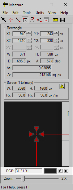
The bottom portion of the magnifier contains a color readout. This readout consists of a color swatch and color value. The color represents the pixel under the cursor or at the center of the crosshair depending on the current measurement tool. The color value can be copied to the clipboard using the button with the clipboard icon immediately to the right of the color swatch.
The color of a pixel can be matched to one of the web extended or web basic colors defined by the W3C. See the description of the color matching formats for details.
- Changing coordinate systems
-
Meazure provides two ways to change the coordinate system used for measurements. First, the y-axis can be inverted so that the origin of the coordinate system is at the bottom of the screen with the y-axis pointing up. Second, the origin of the coordinate system can be moved to a new position.
- Save the position of a measurement tool
-
There are two ways to save the position of a measurement tool: profiles and position logs. The one you choose depends on exactly what you are trying to save.
- Profiles
-
The positions and display characteristics of all measurement tools can be saved to a profile file. These profiles can be loaded anytime to restore the configuration of all measurement tools. In addition, a profile can be specified to be automatically loaded when Meazure is started.
- Position Logs
-
The position of the current measurement tool can be recorded in a position log. This log can be save to a position log file. A position log file differs from a profile file in the following way. A profile file is designed to save a complete snapshot of the Meazure program. That is, all tool positions, appearance settings, calibrations, and all other preferences are saved in a profile file. In contrast, a position log file records the position of the current measurement tool at a point in time and includes only those supporting items necessary to replay the positions.
Meazure makes it easy to capture portions of the screen to the clipboard.
Copyright © 2022 C Thing Software
