Cartographic Options
LTVT function details.. Main Screen.. Tools menu..
This submenu provides options that permit users to customize the mapping style. Additional choices related to the representation and labeling of feature dots can be found under Dot Preferences.

-
1. Those who have loaded the JPL Ephemeris files and wish to use LTVT primarily as an observing guide may wish to check this box. It asks the program to automatically click the Now button in the Main Screen every time the program starts.
-
2. The Vertical Axis options set the overall orientation of the maps
- Cartographic draws maps with the central meridian of the complete Moon vertical
- Line of Cusps draws maps with the terminator vertical
-
Equatorial draws maps with the direction towards the North Celestial Pole (the current direction of the Earth's spin axis) vertical
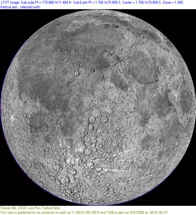
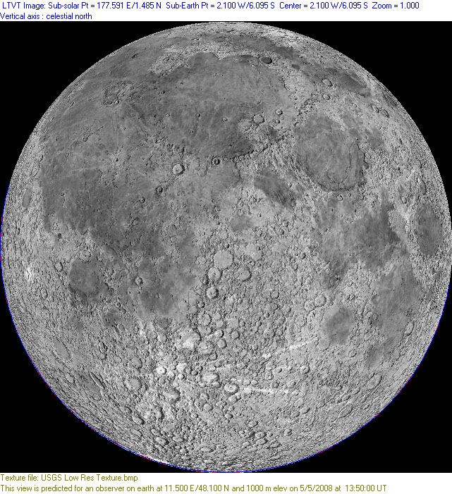
- Here are simulations of the very slender crescent observed by Martin Elsässer on May 5, 2008, as the Moon moved close to conjunction with the Sun, using a digital camera on a telescope with an equatorial mount and the sensor aligned so that the rows and columns of its pixels were parallel and perpendicular to the telescope's directions of tracking the Right Ascension and Declination. These correspond to Martin's images at 10:51 (UT+2) and 15:50 (UT+2). Note that the center of the crescent rotates rapidly around the limb, but the lunar features move very slowly in this orientation. If the camera was aligned carefully enough it should be possible to correlate the images with the simulations and determine what features were on the limb and the locations of the bright and dark streaks (click on the thumbnails to see full-sized LTVT screen shots).
-
*   **Local Zenith** draws maps with the direction towards the observer's zenith (the local vertical direction as determined by a plumb bob) vertical
    *   This example shows a typical night of simulated naked eye Moon orientations as seen from Jim's house, with the Moon rising in the East with its north polar features to the left, transiting with them near the top and setting (in the West) with them to the right. The intermediate orientations are not a steady interpolation between these. In fact the Moon appears to rotate (relative to the zenith direction) much faster when it is near transit, and (on this occasion) actually rotates in the opposite direction when it is very close to the horizon.
-


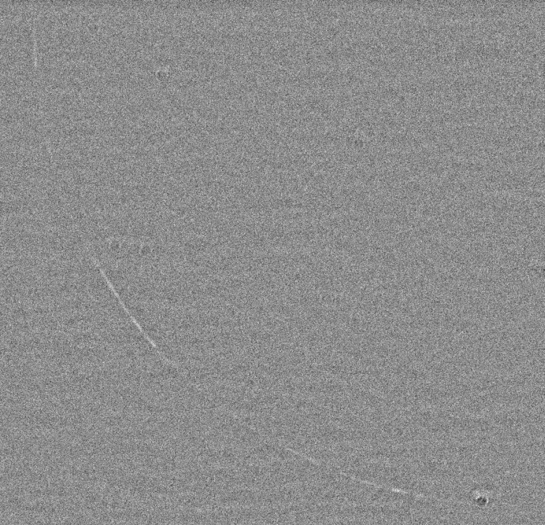
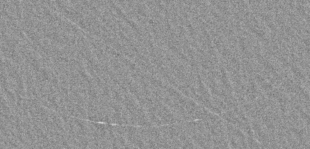
- This example is a close-up from an image by Paolo Lazzarotti that includes peculiar linear striations. The striations were originally reported as being at a 20° angle; but when remapped with LTVT so that the local zenith at the time of the observation is vertical, it can be seen that they were in fact very nearly horizontal.
- This example is a close-up from an image by Paolo Lazzarotti that includes peculiar linear striations. The striations were originally reported as being at a 20° angle; but when remapped with LTVT so that the local zenith at the time of the observation is vertical, it can be seen that they were in fact very nearly horizontal.
-
Note: the orientation modes apply to the whole Moon, and it is rotated about its apparent center. If one wants to change the mode while viewing a small part of the Moon it is best to right-click on the desired center point and select Center On.
-
3. Inversion Options : as the captions indicate, these request left-right and up-down inversions (mirror images). They are primarily useful for duplicating the views in telescopes with mirrors. Selecting both at the same time is equivalent to rotating the image 180°.
-
4. Circle Options: drawing the libration circle (the line of +/-90° longitude, which separates average near and farside hemispheres) and the terminator lines is optional.
-
5. Color Choices ; The Grid/libration circle color is used when lines of constant longitude and latitude are superimposed on the map. Sky Color is used for pixels off the disk of the Moon. Calibrated photo no data color is used for pixels on the Moon's disk, but in areas outside those covered by the photo currently being used to paint the lunar features. Sunlight Side and Shadowed Side Colors are used for shading the schematic lunar disks created in the Dots mode.
-
6. Shadow Measurements Line Length permits the user to customize the length of the line drawn towards or away from a shadow point in the shadow measurement mode.
-
7. Save/Restore permit all options on the present page to be stored for automatic loading the next time the program is started or the Restore option is selected.
-
8. OK/Cancel determine whether the latest changes made to the present page will be applied to the current image or ignored.

This page has been edited 3 times. The last modification was made by -  guest (66.81.16.164) on Nov 15, 2008 7:15 pm