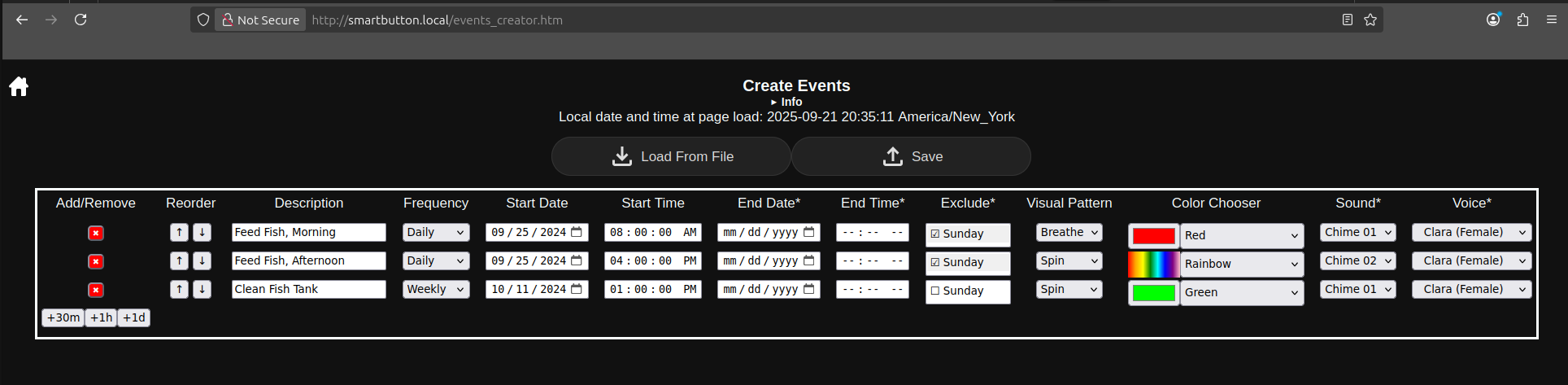
An ESP32 based event scheduler that gives visual and aural notices using LEDs, mp3s saved in flash, and a free TTS service. The case is a big, 3d printed button with a clear cap to show the LEDs.
demo_video.mp4
There are two different ways you can load the code and example files onto the ESP32.
Method 1
Use a browser that supports Web Serial and program the ESP32 board with this page.
Method 2
Download this repository and open it in PlatformIO.
Compile and upload the code.
Click the ant icon on the left hand side, under Platform, click Build Filesystem Image, then click Upload Filesystem Image.
ESP32 D1 Mini - USB C - Aliexpress
ESP32 D1 Mini - USB C - Amazon
FCOB LED strip - 5 mm width - Amazon
Common WS2812B LED strip - Amazon
Max98357 I2S 3W Class D Amplifier - Amazon
Normally open momemtary push button with a tall, 6 mm plunger
Speaker - salvaged from an old desktop
ESP32 to LED strip wiring:
IO16 -- Green -- DIN
GND -- White -- GND (use the GND next to IO0)
VCC -- Red -- 5V (use VCC next to IO2)
ESP32 to Max98357 board wiring:
IO22 -- Orange -- LRC (wclkPin)
IO21 -- Yellow -- BCLK (bclkPin)
IO17 -- Green -- DIN (doutPin)
VCC -- Red -- Vin
GND -- Black -- GND
ESP32 to push button wiring:
IO26 -- Green -- SW_IN
GND -- Black -- SW_OUT (use the GND next to TXD)
Max98357 board to speaker wiring:
+ (plus) hole -- Green -- + (plus) pad
- (minus) hole -- White -- - (minus) pad
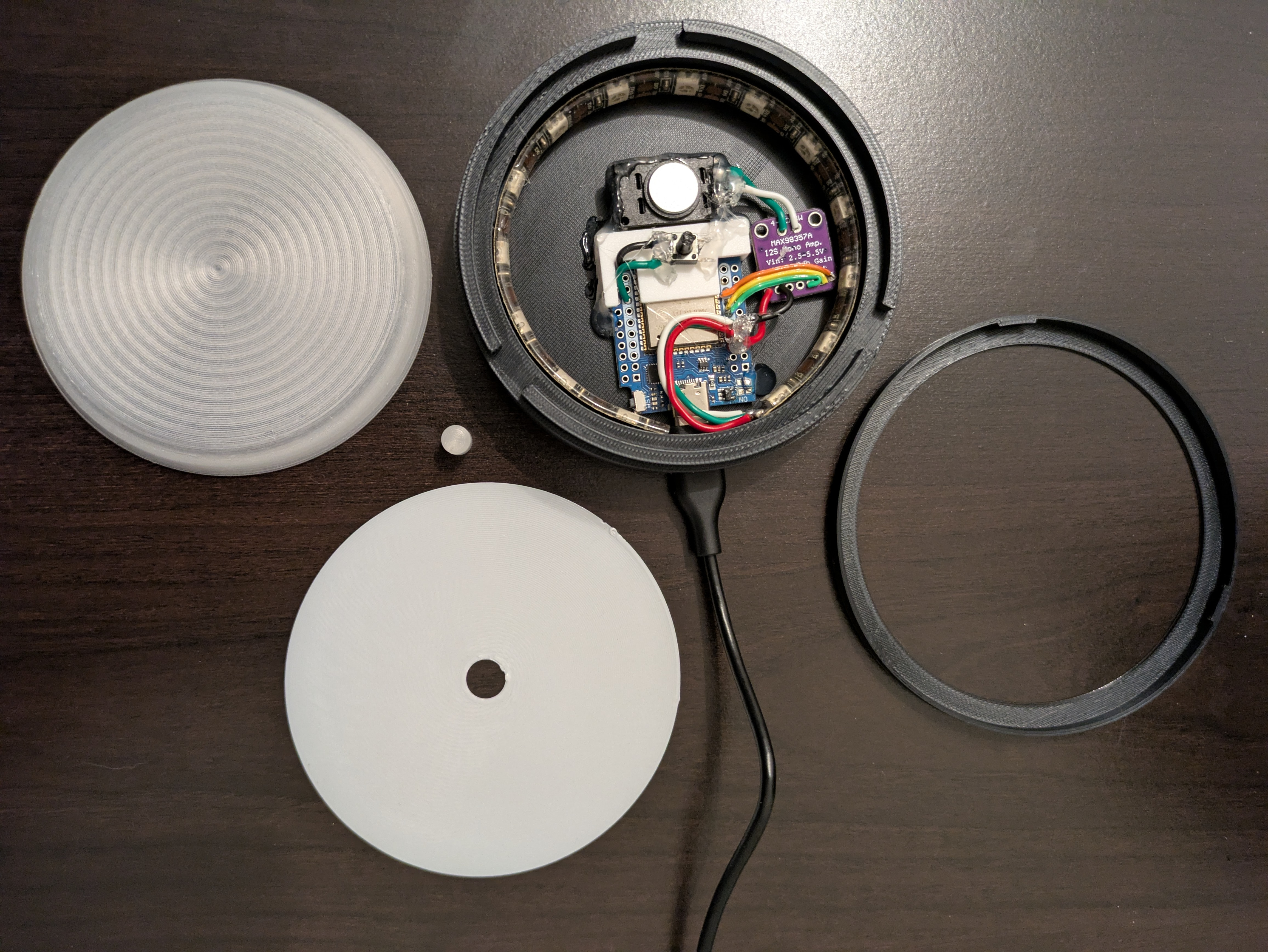
Large button cap and plunger hat are printed in a clear PLA.
Push button support and diffuser are printed in white PLA.
The base and retaining ring are printed in black PLA.
The button cap and diffuser were printed using the following settings in Orca Slicer:
Quality
Seam position: Random
Strength
Top surface pattern: Archimedean Chords
Bottom surface pattern: Archimedean Chords
Sparse infill pattern: Archimedean Chords
Internal solid infill pattern: Archimedean Chords
Others
Reduce infill retraction: unchecked
Reduce infill retraction prevents stray bits of filament being visible in the infill since the filament is clear.
A layer height of 0.12 mm was used for the button and 0.2 mm was used for the diffuser.
The device can create its own WiFi network or it can connect to your established WiFi network. You can control the device by connecting directly to its WiFi network, but you will be able to access the device more easily and be able to use the time and date features if you connect it to your WiFi network.
Find the WiFi network named SmartButton and connect to it. You may get a dialog message like: "The network has no internet access. Stay connected?" If so, answer Yes. I do not recommend marking the box "[ ] Don't ask again for this network" In a web browser, open the site smartbutton.local or 192.168.4.1. Open the Configuration page. Enter your WiFi network information (SSID and password). The rest of the fields may be ignored for now. Click Save. The device should restart and connect to your WiFi network. The SmartButton WiFi network should no longer be visible in your list of available networks. It will appear again if the device no longer has access to your WiFi network (e.g. password changed).
Now any computer or phone on your WiFi network will be able to control the device be visiting smartbutton.local.
LEDs config
LEDs number is the count of LEDs in your strip.
LEDs offset is the LED index you want to treat as if it was the start of your LED strip. Since there are physical limitations on where the actual start of the strip can be, the software lets you shift the apparent location of LED 0 to make the visual patterns have a more pleasing orientation.
VoiceRSS API Key
Voice RSS offers a free API key for their TTS service with a limit of 350 requests per day. The sign up process is simple and only requires an email address.
Setting the timezone
If you want to use UTC time then nothing further is required.
If you would like to use your local time:
Go to smartbutton.local again and open the Configuration page.
Delete the information in the IANA Timezone field, and click outside of that field.
With luck your IANA Timezone will be filled in automatically based on the location of your IP address, then a few moments later the POSIX Timezone (has Daylight Saving Time info) will also automatically be filled in. If this information is not correct you can manually set the IANA Timezone, then the POSIX Timezone will automatically update.
Click Save and wait for the device to restart.
Now you should be able to add the time and date to your composites.