Archive
This is the archived versions. Newer versions are in the Releases article.
Schematic and gerbers are in the releases file section.
This is the only board that uses internal nRF5x voltage regulator (VDDH mode). There's one kind of major issue - you can't flash bootloader via Bluepill without soldering power directly to 3.3V (it runs at 1.8V core voltage by default), there's no 3.3V testpoint so you have to solder directly to the top pad on the Bluetooth module. J-LINK programmers apparently don't have this issue.
- Midmount USB-C connector for 1.6 mm PCBs
- 10 uH inductor (0603 package)
- MCP73811 (should also work with an old MCP73821, with software PROG pulldown for 100 mA)
- Schottky 1N5819 diode is now SOD-323 (smaller)
- 820K and 2M resistors (0603 packages) for the battery voltage measuring circuit


Note CHG_EN (the proper name would be STAT_PIN) does NOT enable or disable the TP4054 or MCP73831/2 charger, it only matters for MCP73811 (rare digital charger). You can forget about this pin if you're using TP4054, the only charger pin that matters is CHG_PROG aka PROG_PIN (same method as in 1.3, except there's no pulldown resistor, so it's either float or pull-down with internal 13K, never zero).
-
https://devzone.nordicsemi.com/f/nordic-q-a/19527/shall-i-leave-the-lc-filter-attached-to-dcch-pin-alone - The nRF52840 has two voltage regulators, one for high voltage (2.5-5.5V) and one for low voltage (1.7-3.6V). These two regulators have two operation modes: LDO or DCDC. With the DCDC mode you need to add an external inductor (between DCCH and VDD). If your input voltage is lower than 3.6V you can skip regulator 0 and connect VDDH and VDD together (see figure 2). The reference layouts will also show you the different configurations. We strongly recommend that you follow the reference layout as much as possible.
-
https://devzone.nordicsemi.com/f/nordic-q-a/35178/dc-dc-converter-on-nrf52840 - The only requirement is that you also populate a 10µH and a 15nH inductor between DCC and DEC4 pins (single 10µH for REG0 DC/DC). See the DC/DC option in the reference layout. Once populated the DC/DC converter is then enabled either by writing to NRF_POWER->DCDCEN if you are not using our Softdevice, or by calling sd_power_dcdc_mode_set() if you are using the Softdevice. Once enabled, the power management unit will lautomatically configure the power system for operation mode that is most efficient for the current load and active components.
To flash the board you have to power it from VCC/GND pins directly, it won't flash in 1.8V mode. This is very annoying, considering there's no VCC testpoint on 1.2 so you have to solder 3.3V from the programmer directly to the VCC pin of the module.
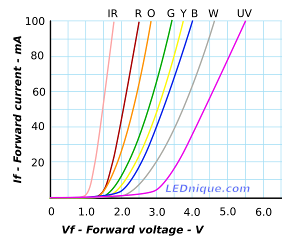
Due to the low 1.8V core voltage we can't use regular onboard LED, voltage drop is too high. Blue LEDs don't work, green LEDs are super-dim, the best brightness you get with the red onboard LED.
- https://www.circuitbread.com/ee-faq/the-forward-voltages-of-different-leds
- https://www.petervis.com/electronics/led/led-resistor-calculator.html
Upd. 0603 blue LED consumes 0.694 mA via 1K resistor with 3.3V core voltage, green LED consumes 0.910 mA.
nRFMicro schematics supposed to work in High Voltage Mode (there's 10 uH inductor), but internal DC-DC is not enabled since BOARD_ENABLE_DCDC_HV is not enabled in firmware so it uses internal LDO instead of DC-DC.
There's no regulator on the board, meaning VCC output is unregulated 3-5V from the battery/USB selector.
The internal regulator (usually set to 1.8V core) power is up to 25 mA. If you use it as VCC for RGB keyboards (up to 500mA) it will probably burn. One could just pass through the lipo to the keyboard LEDs and OLED screens. 3-5V range should be fine.
Also see Pinout#power-pins for details.
Power MOSFET can't close 5V output at 1.8V core (-3.2V base). Works with 3.3V core/3.8V battery.
- Revision 1.1 with EXT_GND doesn't have this problem at all.
- Revision 1.2 is affected, partial fix with a 3.3V core voltage
- Revision 1.3 with 3.3V core and 3.3V input/output should be fine.
Tried setting 3.3V core voltage. Status LED is now much brighter, mosfet still doesn't close from USB.
  if (NRF_UICR->REGOUT0 != UICR_REGOUT0_VOUT_3V3) {
    NRF_NVMC->CONFIG = NVMC_CONFIG_WEN_Wen << NVMC_CONFIG_WEN_Pos;
    NRF_UICR->REGOUT0 = UICR_REGOUT0_VOUT_3V3;
    NRF_NVMC->CONFIG = NVMC_CONFIG_WEN_Ren << NVMC_CONFIG_WEN_Pos;
  }
It only closes at about 3.8V on the battery and 3.3V core voltage. Video:

-
Some keyboards (e.g. HHKB Pro 2, see hhkb_ble) want regulated 3.3V for the peripherals to work reliably. That would need an LDO voltage regulator on the board. The advantage of LDO is that there's EN pin so you could get rid of the power mosfet, the disadvantage is that LDO doesn't work in reverse so you would need to add another schottky diode for the TRRS input.
-
Mind that LDO can't boost voltage up, it only pushes voltage down. So you can't get 5V from a 3.7V Li-Po battery without a step-up or boost converter. Those things usually include a coil inductor that's way too large for the Pro Micro-sized board and not very energy efficient.
Charger can be briefly switched off to read and display the Li-Po's actual value while charging.
Current 1.2 schematic uses MCP73811 charger by default - it has a separate EN pin and its PROG pin sets the charging current, 0 - 85 mA, 1 - 450 mA. You can also use MCP73831, which is disabled by setting PROG input to float (high-z) and 13K software pull-down on PROG sets ~77 mA current.
MCP78311 charger (marked KSB7) doesn't work as expected (see jorne_ble.c). Logical 1 on the PROG pin doesn't enable 450 mA charging current, but sets output to 0V, logical 0 sets output to 4.2V (tested without the battery). STAT pin (EN pin) doesn't seem to affect anything at all. Looks like it works similar to MCP3831 or TP4056 chargers (maybe part mismatch), so shorting PROG to ground might be bad (internal pulldown works fine, but I'm not sure about the charging current). Maybe fake part.
This it the case when you use a wired configuration and power the other half via TRRS (basically via the EXT_VCC pin). There's a P-MOSFET body diode on the way. Voltage drop is about the same 0.7-1V as on regular diodes (it is also fairly slow). Dedicated 1N5819 (if any) would be about 0.6V. Probably doesn't worth a dedicated diode.
- Simulation: http://tinyurl.com/y8qwgr9a

Note that P-FET needs active pin high to disable EXT_VCC (opposite to N-FET and EXT_GND). MCU retains GPIO states in off mode, so it should be fine. Will also try internal pull-up/pull-down modes.
Aside from super-tight tolerances in 1.2 that need a fine soldering tip and soldering external 3.3V for flashing the bootloader, I somehow managed to fry the nRF52840 while testing the board (VCC is now shorted to GND). I blame High Voltage mode (maybe accidently shorted 5V to something). Large caps seem okay. Some of the smaller capacitors are shorted, not sure if it's caps or MCU, checking 0201 caps could be problematic because they're just so small. Second board worked okay though. Related issue:
Schematic and gerbers are in the releases section.
This is first release version featuring reversability, onboard On/Off switch and a voltage divider for measuring battery charge. There are almost no issues except battery gauge is kind of leaky (10K/13K divider leaks about 4.2V / 23K = 0.18 mA) but the 13K is the internal pull-down pin so you can turn it off in software by setting it to float (input with no-pull).
PCB gerbers for version 1.1 are also published on PCBS.io. I tried OSHPark's "After Dark" option (clear mask, black substrate) but the black mask on PCBS.io seems more practical. You may download or order it here:
- https://pcbs.io/share/46enW ($3.77 for 4 pcs, free international shipping from Miami FL, preferred)
- https://oshpark.com/shared_projects/4ov7EnoB (better quality, $4.70 for 3 pcs with shipping)
You can use either Aliexpress or LCSC (the latter was shipping JLCPCB boards in the same box). Mind that LCSC doesn't usually have E73-2G4M08S1C modules and MSK-12C02 switches in stock. Latest LCSC-compatible BOM: nrfmicro_0_03_BOM.xlsx.
I'd really recommend Vanxy Aliexpress store instead of LCSC. Small components for 10 boards cost about $10, and for extra $2 you can ship them all in a single package with a trackable shipping.
| Name | LCSC PN | Qty | Package | Value | Description | Aliexpress |
|---|---|---|---|---|---|---|
| U1 | C331405 | 1 | SMD | 2G4M08S1C | E73 nRF52840 | $3-$5 / 1 |
| J2 | C165948 | 1 | SMD | MC-372 | USB-C 16-pin | $0.19 / 1 |
| R1,R3 | C14675 | 2 | 0603 | 100K | SMD Resistor | $0.61 / 100 |
| R2,R8,R9 | C98220 | 3 | 0603 | 10K | SMD Resistor | $0.61 / 100 |
| R4,R5 | C105580 | 2 | 0603 | 5.1K | SMD Resistor | $0.61 / 100 |
| R6,R7 | C22548 | 2 | 0603 | 1K | SMD Resistor | $0.61 / 100 |
| D3 | C84263 | 1 | 0603 | Red | SMD LED | $0.87 / 100 |
| D2 | C84266 | 1 | 0603 | Blue | SMD LED | $0.87 / 100 |
| C1,C2,C3 | C1691 | 3 | 0603 | 10uF | SMD Capacitor | $1.69 / 100 |
| Q1 | C351408 | 1 | SOT-23-3 | AO3407 | P-MOSFET | $0.95 / 50 |
| D1 | C82544 | 1 | SOD-123 | 1N5819 | Schottky Diode | $0.84 / 100 |
| U3 | C51118 | 1 | SOT-23-5 | AP2112K-3.3 | VCC Regulator | $0.81 / 10 |
| U4 | C14879 | 1 | SOT-23-5 | MCP73831 | Li-Po Charger | $1.02 / 10 |
| Y1 | C13712 | 1 | TH 2*6mm | 32.768KHz | Crystal (opt.) | $0.87 / 10 |
| J1 | C40943 | 1 | 5P | 5P 4 legs | MicroUSB (opt.) | $0.46 / 10 |
| SW1 | C16168 | 1 | SMD | MSK-12C02 | SPDT Switch | $1.31 / 10 |
| Q2 | C88051 | 1 | SOT-23-3 | AO3406 | N-MOSFET | $0.95 / 50 |
- Blue LED comes with Red LED (5 colors 20 pcs each, you also get other colors)
- The 32.768 kHz external crystal is optional (QMK firmware does not use it), also see 1610 ones
- MicroUSB is an option to replace USB-C (you can solder either of those)
Revision 1.1 is precisely the same as 1.0 but 0.26 is internally connected to 0.04 (analog pin) to read battery voltage.

Put some kapton tape over MicroUSB pads before soldering top-mount USB-C (revisions 0.01 to 1.1). It works fine without that (there's a small gap) but it's better to make sure that they are insulated.
Revisions 0.03 to 1.1 use 16 solder jumpers to keep the antenna side up. This is used to maximize drop-in compatibility (many split keyboards use upside down mounted Pro Micros) especially if hotswap headers are already pre-soldered.
- regular Pro Micro - solder jumpers on the antenna side (bluetooth module side)
- flipped Pro Micro - solder jumpers on the on/off switch side (keeps antenna side up)
Top 4 rows of pins can be flipped by those jumpers, bottom 8 rows of pins could be just remapped, see custom_board.h (build with CFLAGS +=-DFLIPPED_NRFMICRO).
Newer revisions don't have those jumpers and supposed to be installed antenna side down.
Pin legends match pins only on the side where you have those solder jumpers soldered.
Onboard Red LED should blink if battery is not connected or the power switch is off, it's normal (it's wired directly to the charger). Onboard Blue LED is internally connected to the unused pin (P1.10) and controlled from firmware.
There's an issue with Reset because GND is off by default, use tweezers on B- and RST instead of GND and RST to reset the module (double reset to open the USB drive). Software solution would be checking if usb is USB plugged in and enabling the power automatically (fixed in latest firmware). You can also send "dfu" to the serial port. Affected revisions are 1.0 and 1.1.
nRFMicro powered directly from VCC pin (from TRRS) affects switch pin status. I have no idea why. Something to do with the software pulldown on 0.26 or the ADC PWM on 0.04, I guess. Kind of a serious issue, because switch pin is responsible for switching between USB/BT modes. Possible solution would be reading analog ADC data from pin 0.04 (check if it's more than 1V). Video: https://youtu.be/RLjTftCp_GA

The way it works now is there's always a wireless connection between the slave and the master even if the master is in USB mode and both batteries are off. I just can't determine if battery is off because switch pin (aka battery presence pin) on the slave half is always 1. I'll fix that in the upcoming 1.2.
Regarding TRRS vs TRS - not sure if 3-wire cable transport actually works now, the firmware seems to have 4-wire I2C-transport only, no serial duplex (I don't have an I2C-compatible keyboard at the moment). But it's a VCC-only issue so transport doesn't really matter.
Making wireless Jorne Classic 2.1 with nRFMicro 1.1:

- https://youtu.be/ZUOJoJSWu-E video from jpconstantineau about E73 soldering
- https://youtu.be/3ojTlSJr4NA another video from jpconstantineau
- https://youtu.be/7bNX6ZIGcIc assembling nRFMicro 1.1
- https://youtu.be/CsANtp6a3YU assembling a wireless keyboard
Youtube search: https://www.youtube.com/results?search_query=nrfmicro
- https://oshpark.com/shared_projects/qKXfBu0d
- Added power mosfet
- Added battery pins
- Bridge pin 0.26 to pin 0.04/AIN2 using a piece of wire to read the battery voltage from the analog pin (affected versions 0.03 and 1.0, fixed in the upcoming 1.1.)
- https://pcbs.io/share/rEVPb
- https://github.com/joric/nrfmicro/releases/download/0.03/nrfmicro-0.03-gerbers-oshpark.zip
- https://github.com/joric/nrfmicro/releases/download/0.03/nrfmicro-0.03-gerbers-pcbs-io.zip
- Fully reversible design with solder jumpers, doesn't matter which side is up
- Hardware Bluetooth/USB modes switch support with a dedicated mode pin
- Convenient status LEDs placement (on the front edge of the board)
- Keepout area for the better antenna reception
| Item | Pcs | Total | Paid | Shipped | Received | Days |
|---|---|---|---|---|---|---|
| SMDs from Vanxy | 1 | $11.38 | 2019-04-23 | 2019-04-27 | 2019-05-06 | 13 |
| PCBS.io PCBs 0.03 | 4 | $3.77 | 2019-04-23 | 2019-05-02 | 2019-05-14 | 21 |
| 2G4M08S1C Modules | 2 | $14.78 | 2019-04-23 | 2019-05-05 | 2019-05-17 | 24 |
- PCBs are published on PCBS.io: https://pcbs.io/share/rEVPb ($3.77 for 4 pcs with shipping, total)

- Version 1.0 needs bridging 0.26 to analog pin (0.04/AIN2) to read the actual battery voltage (versions 1.1+ already use 0.04).
- See Soldering article about solder jumpers.
- Full Type-C support including both PD and QC cables (also supports optional MicroUSB)
- 0.85mm drill holes to provide spring-loaded pin headers support
- https://oshpark.com/shared_projects/Oe5Xs77v
- Hardware USB support with E73-2G4M08S1C (nRF52840), both Micro-USB and USB-C
- Small size MCP73831 (SOT23) and AP2112K-3.3-based LiPo charger and power circuit
- Optional Crystal (2-pin, 32.768khz) and battery ON/OFF switch (MSK-12C02)
| Item | Pcs | Total | Paid | Shipped | Received | Days |
|---|---|---|---|---|---|---|
| 2G4M08S1C Modules | 2 | $14.78 | 2019-02-18 | 2019-02-19 | 2019-03-06 | 16 |
| OSHPark PCBs 0.01 | 3 | $4.70 | 2019-02-23 | 2019-03-06 | 2019-03-23 | 28 |
- Move battery signal from 0.26 to analog pins (0.02-0.05 or 0.28-0.31) to actually read voltage (you can probably bridge 0.26 to the analog pin 0.04/AIN2 on the backside). See details here.
- Use Goldfish-style Type-C midmount for the next generation, e.g. from Aliexpress, $1.15 for 10 pcs (USB-C is way taller than everything else on the board, even the shielded module).
- Add power control mosfet to disconnect power-hungry switchboards such as HHKB Pro 2
- PCBA setup, see PCBA article
- High voltage supply option for nRF52840 (needs an inductor between VCC and DCCH and enabled DCDCEN0 register to activate the internal DC/DC converter, default is DCDCEN1).
- Maybe remap pins the way it would not need to solder underside pins at all? There would be 18 GPIOs on the outer edge if we reuse XL1/XL2 and P0.18 (RESET) pins (see Pinout). Reusing RESET might be impossible though.
ONLY if you need to modify and reexport the board! Manually replace all oval pads with 4-5 round pads (PCBS.io needs round holes on the drill layer), and use the following plot settings:
- disable "Edge.Cuts" layer, enable "Margin" layer (make sure it matches Edge.Cuts)
- enable "Exclude PCB Edge layer from other layers", "Use Protel filename extensions"
- (drill file) enable "PTH and NPTH in a single file"
Note: PCBS.io doesn't support plated oval slots, use series of round drills instead.
As of 2020-02-27 PCBS.io supports edge cuts but I'm still not getting proper oval slots, they must be properly pre-drilled.
Soldering and flashing nRFMicro 0.03 (https://youtu.be/hTTLyR1nII0):

Note power mosfet gate is floating if POWER_PIN is unintialized, so you can get random voltage (e.g 1.7V) on EXT_VCC, that rapidly discharges to zero. You need explicitly set POWER_PIN to 0 or 1 to enable or disable EXT_VCC.
With nRFMicro 1.3 make sure PROG_PIN is set to LOW by default. Never set PROG_PIN to HIGH, that may damage the charger. Possible states are: output with LOW (10K resistor to GND, enables the charger), input with NOPULL (high-z, disables the charger), input with PULLDOWN (adds internal 13K resistor to the onboard 10K resistor, sets current to about 45 mA).
If you hold a key with tweezers and touch diode pads with bare fingers it presses random keys. Some neighbor keys are pressed simultaneously (e.g. RGB_MOD presses DELBNDS key). I have no idea why it happens. Maybe it's the lack of capacitors on the 1.3 comes into play. All soldered 1.3 modules are affected (PCBWay batch). Figures that 1.4 and generally all the boards are affected too so it's a common issue.
- ONLY bare thingers and tweezers are affected (discovered 2020-08-11)
- Note the very same keyboard works perfectly fine with regular Pro Micro (Jorne 2.1)
- It is a little bit less severe on battery power than on USB power (why?)
- All firmware is affected (not a QMK issue, Bluemicro too).
Video: https://youtu.be/X0pHlg528f8

What I tried to fix this issue (related image https://i.imgur.com/gGsFvIG.jpg):
- Soldered 10uF before AP2112K (filters LDO input, LDO output is already filtered with built in 4.7uF)
- Soldered 10uF between RAW and GND (filters the battery)
- Soldered 2M pull-down resistor for power output mosfet (pulls down floating gate)
- Desoldered TP4054 entirely
That didn't help. I got absolutely no results whatsoever. Not yet tried (in no particular order):
- Add even more caps? 3 caps perhaps, as in 1.1, including VCC cap?
- Checking all the pins for shorts/floating/feedback (maybe same issue as with the floating power mosfet)
- Soldering back the shielding, maybe removing the shield somehow affects continuity of the ground plane
- Desoldering RGB LEDs or trying a new keyboard without RGB (doesn't seem related)
- Replacing all the keyboard matrix diodes from 1N5819 I use to 1n4148 or something (works fine with Pro Micro though)
Upd. reportedly changing diode direction in software to col2row fixes the issue. Then swap col and row pins.
There are no capacitors on the 1.3 board. E73 modules already has a few large 4.7uF inside the module, one is on the VDD pin. So all the regulated stuff on the output is covered with a large 4.7 uF cap.
As for USB input for TP4054 (MCP73831) the reason for the input capacitor is to ensure that the chip is stable and doesn't oscillate. Those issues are commmon with bad switched mode PSUs but USB should be perfectly stable. Also the battery works as a capacitor, doesn't really need one.
1.3 footprints are kind of messed up for the JLCPCB SMT assembly I guess. Too much overlapping courtyards. Couldn't do it without overlapping. It's probably fixable with 0402 resistors, they have some 0402 parts in the basic catalog.

The design was mostly about easy soldering and cheap components. Moving towards PCBA could change a few things.
A few ideas (in no particular order, no ETA):
- Use a combined (anode anode cathode) schottky diode such as BAT54C to do usb/battery switching rather than the schottky/mosfet/pull resistor combination favored by adafruit/nicenano. Leaks more than the mosfet switch though.
- 2021-05-09 - 1.4t branch tested (not me). Pictures: jorne v3, 2.1, PCBs. Moved SW1 0.4 mm up.
- 2021-02-02 - Soldered/tested 6 nRFMicro 1.4. FML. https://i.imgur.com/OZ6HEce.jpg https://i.imgur.com/T6hbzya.jpg
- 2021-01-29 - nRFNano 1.0 picked up. Everything works except radio (VSS_PA?): https://youtu.be/xmzxtMZCiEU
- 2021-01-11 - nRFNano 1.0 shipped ($41.16 total, $34.39 for parts and $6.77 shipping), see picture
- 2021-01-04 - nRFNano 1.0 (PCBA version with PCB USB-C connector and nRF52840 in AQFN-73) ordered on JLCPCB
- 2020-12-22 - Added new board BluePhage by /u/southpawengineer to the Alternatives section, check it out.
- 2020-12-18 - Got 0.8mm 1.4 PCBs from PCBWay, took 50 days. Drills are fine, good silk resolution. my picture
- 2020-12-05 - JLCPCB got nRF52840 https://jlcpcb.com/parts/componentSearch?searchTxt=nrf52840. See PCBA.
- 2020-11-28 - Another failed PCB from OSHPark (old batch, fixed now). Not my picture: https://i.imgur.com/99t82Xc.jpg
- 2020-11-20 - Updated nRFMicro 1.4 OSHPark and gerbers because JLCPCB cuts through drills (-0.15mm) (not my picture).
- 2020-11-07 - Updated nRFMicro 1.4 OSHPark and gerbers because OSHPark messes up multiple drills (not my picture).
- 2020-10-29 - 1.4 PCBs ordered from PCBWay, https://www.pcbway.com/project/shareproject/nRFMicro_1_4.html
- 2020-10-15 - Looks like nRFMicro 1.4 is fully operational, pushed to master (I haven't tested them personally).
- 2020-10-14 - First nRFMicro 1.4 soldered and checked by Ariamelon, seems to work fine, now in testing stage.
- 2020-10-12 - 1.4 PCBs ordered from PCBS.io
- 2020-09-29 - Created devel-1.4 branch, based on PR #28 by Ariamelon (thanks!) lots of good changes, still untested.
- 2020-08-19 - Rolled out nRFMicro 1.3 as default release because it's thinner and needs fewer parts and mostly works.
- 2020-08-11 - Great success, figures there's no matrix capacitance issue in 1.3 if you don't use tweezers!
- 2020-08-04 - Got 1.3 PCBs from PCBS.io (took 54 days overall) https://i.imgur.com/SWukCEf.jpg
- 2020-08-03 - Weird problem in 1.3. Video: https://youtu.be/X0pHlg528f8. Don't know how to fix yet.
- 2020-07-28 - Fixing 1.3 firmware (RGB_MOD calls DELBNDS for some reason), floating EXT_VCC (fixed), video.
- 2020-07-26 - Soldered 1.3 - stencil, hot air, 4 TH for USB-C (pic). Charger/radio/internal GPIOs work. Now testing.
- 2020-07-24 - Etched stencil for 1.3 (pic1, pic2, pic3), see this tutorial: https://youtu.be/JWUJtmgh55M.
- 2020-07-21 - Got 1.3 PCBs from PCBWay (took 38 days), now up to soldering and some testing.
- 2020-07-11 - A couple of 1.3 soldered by NOT ME, charger works, VCC switch works, master/slave work. pic
- 2020-07-01 - First 1.3 soldered by NOT ME, USB works, advertises via Bluetooth. pic.1 pic.2 pic.3
- 2020-06-30 - 1.3 PCBs shipped from PCBS.io
- 2020-06-16 - 1.3 PCBs shipped from PCBWay
- 2020-06-13 - 1.3 PCBs ordered from PCBWay
- 2020-06-11 - 1.3 PCBs ordered from PCBS.io.
- 2020-06-10 - Drafted 1.3 pre-release (3.3V regulator mode, no inductor).
- 2020-06-08 - Soldered 1.2 PCB. Seems to work fine except the need for the external 3.3V source for SWD.
- 2020-06-05 - Got 1.2 PCBs from JLCPCB ($5 for 30 pcs). Now up to soldering and some testing.
- 2020-05-14 - Drafted 1.2 pre-release (high voltage mode, no AP2112K), ordered PCBs for testing.
- 2020-05-09 - Ordered 1.2 alpha boards (sadly no 2-nd schottky for powering from TRRS)
- 2020-05-07 - RGB sync, eeprom.c from https://github.com/chie4hao/qmk_firmware_nrf52840
- 2020-04-23 - experimental 1.2 PCBs shipped out from PCBS.io
- 2020-04-13 - got PCBs version 1.1 from PCBS.io
- 2020-03-16 - PCBS.io shipped PCB version 1.1 (4 pcs)
- 2020-03-11 - ordered nRFMicro 1.2 (devel branch) on OSHPark (clear mask, black substrate)
- 2020-03-03 - added "nrfMicro V2" to the Alternatives article, check it out!
- 2020-02-27 - version 1.1 pushed to master (added connection between 0.26 and 0.04), untested!
- 2020-02-26 - version 1.0 pushed to master, ordered version 1.1 on PCBs io
- 2020-02-24 - power mosfet works (video), LEDs need USB (video), battery voltage works with 0.26 shorted to 0.04/AIN2 (adc.c)
- 2020-02-20 - Got nRFMicros 1.0 PCBs from mail. Now up to soldering and some testing.
- 2020-01-29 - OSHPark shipped 6 nRFMicro PCBs (After Dark, clear mask on black substrate, pic)
- 2020-01-16 - pcbs.io seems lost, reordered nRFMicro 1.0 boards on OSHPark (see devel branch)
- 2019-11-05 - nRFMicro 1.0 PCBs shipped from pcbs.io, tracking number created
- 2019-11-02 - tried to remove inner pads (minimal-outer-pins branch), but it lacks reset pin
- 2019-10-17 - layouted and ordered devel branch (nrfmicro-1.0, with an extra mosfet, Si2036) for free (got $12 credit from referrals on pcbs.io, thank you guys!).
- 2019-07-11 - soldered 2 more boards (pic), added testing guide to the Hardware section.
- 2019-07-08 - Built Jorne Keyboard, uploaded a video (https://youtu.be/MHdYclGr3EE).
- 2019-05-20 - PCB 0.03 built and tested, everything works fine. Video.
- 2019-05-17 - Got 2G4M08S1C Modules from mail.
- 2019-05-15 - Got PCBs 0.03 from the manufacturer, USB footprints are OK, maybe fix plastic stems. Silk is mostly fine, needs adjusting. Plated slots look fine (maybe add a common shielding net). Video.
- 2019-05-11 - Tried to implement HHKB Pro 2 controller and realized I need a mosfet to switch off VCC line.
- 2019-05-10 - Added shipping estimate table to the Hardware page, check it out!
- 2019-05-08 - Got SMD components, waiting for 0.03 PCBs from PCBS.io (shipped in 9 days)
- 2019-04-19 - Drafted new release 0.03 with reversible layout (untested)
- 2019-04-12 - Managed to compile and run QMK firmware for the Jian keyboard (fork) (video)
- 2019-04-11 - Soldered everything for the test Jian build. External crystal also works (tested, see the picture)
- 2019-04-10 - Fixed Type-C issues (added CC-pulldowns, flipped footprint), see pictures here and here. Drafted new release 0.02.
- 2019-04-04 - Flashed pca10056_bootloader-0.2.10_s140_6.1.1.hex - USB UF2 updates work (use uf2conv.py), double reset works!
- 2019-04-03 - Type-C does not work! Have to fix Type-C issue in the next revision (see c-pro-micro schematics for example)
- 2019-04-03 - MicroUSB seems to work fine (still needs testing), mass storage works without external crystal.
- 2019-04-03 - Coulnd't find 32K crystal at home so I've set all LF_SRC to 0 and Bluetooth finally worked (most examples use external crystal but this E73 module doesn't have one).
- 2019-04-03 - Uploaded firmware after removing protection (it's either
nrfjprog --recoverfrom J-Link or mass_erase from BMP). - 2019-04-03 - Assembled two pieces, see the pictures.Charger via Type-C works (4.2V on the battery), voltage regulator works (3.3V on VCC), module autodetection works.
- 2019-03-23 - Got PCB version 0.01 from the manufacturer (OSHPark)