Components
This article is NOT about Bill of Materials, it's about component substitutes. See Releases article for BOM. Also see Soldering.

This table helps to check part codes and spot a substitute part. Make sure that both package and description match.
| Datasheet | Code | Package | Description | Comment | Aliexpress | nRFMicro |
|---|---|---|---|---|---|---|
| 2G4M08S1C | S1C | SMD | nRF52840 | 1M Flash / 256K RAM | $3-$5 / 1 | All |
| 2G4M08S1CX | S1CX | SMD + IPEX | nRF52840 | 1M Flash / 256K RAM | $6-$9 / 1 | All |
| 2G4M08S1E | S1E | SMD | nRF52833 (issues) | 512K Flash / 128K RAM | $5-$6 / 1 | All |
| 2G4M08S1EX | S1EX | SMD + IPEX | nRF52833 (issues) | 512K Flash / 128K RAM | $5-$6 / 1 | All |
| 1N5819 | S4 | SOD-323 | Schottky diode | 20V, 350 mA | $0.84 / 100 | >=1.2 |
| BAT60B | SL | SOD-323 | Schottky diode | 10V, 3A | $0.94 / 20 | >=1.2 |
| B0540WS-7 | SF | SOD-323 | Schottky diode | 40V, 500 mA | $2.00 / 10 | >=1.2 |
| MBR0540WS | B4 | SOD-323 | Schottky diode | 40V, 500 mA | $0.85 / 100 | >=1.2 |
| AO3406 | A69T | SOT-23-3 | N-MOSFET | 30V, 4.1A | $0.95 / 50 | <=1.1 |
| 2n7002e | 7ERBC | SOT-23-3 | N-MOSFET | 60V, 240 mA | $6.32 / 50 | <=1.1 |
| Si2302 | A7SHB | SOT-23-3 | N-MOSFET | 20V, 2.8A | $0.95 / 50 | <=1.1 |
| Si2301 | A1SHB | SOT-23-3 | P-MOSFET | 20V, 2.3A | $0.75 / 50 | All |
| Si2305 | A5SHB | SOT-23-3 | P-MOSFET | 20V, 3.5A | $1.50 / 50 | All |
| AO3407 | A79T | SOT-23-3 | P-MOSFET | 30V, 4.1A | $0.95 / 50 | All |
| TP4054 | 54b6 | SOT-23-5 | Charger IC | up to 800 mA | $0.78 / 10 | All |
| LTC4054 | LTH7 | SOT-23-5 | Charger IC | up to 600 mA | $0.60 / 20 | All |
| MCP73831 | KD** | SOT-23-5 | Charger IC | up to 500 mA | $1.02 / 10 | All |
| MCP73832 | KR** | SOT-23-5 | Charger IC | up to 500 mA (High-Z) | $1.99 / 10 | All |
| LN2054 | 2YL6 | SOT-23-5 | Charger IC | up to 500 mA | $0.99 / 10 | All |
| MCP73811 | KSB7 | SOT-23-5 | Charger IC (digital) | Switchable 85/450 mA | $10.34 / 20 | 1.2 only |
| AP2112K-3.3 | G3P | SOT-23-5 | LDO Regulator | 3.3V 600 mA, QC 55 uA | $0.92 / 10 | All |
| LD3985 | 4A2D | SOT-23-5 | LDO Regulator | 3.3V 150 mA, QC 70 uA | $0.82 / 10 | All |
| XC6220 | H633P | SOT-23-5 | LDO Regulator | 3.3V 1A max, QC 8 uA | $4.00 / 30 | All |
| MIC5216 | LH33 | SOT-23-5 | LDO Regulator | 3.3V 500 mA, QC 3-8 uA | $6.54 / 20 | All |
| FC1610AN | A***L | 1610 | 32.768 kHz Crystal | 1.65x1.05mm | $3.37 / 10 | 1.4 |
| FC-12M | DA*** | 2012 | 32.768 kHz Crystal | 2.0x1.2mm | $2.67 / 10 | 1.4 |
| FC-135 | A**** | 3215 | 32.768 kHz Crystal | 3.2x1.5mm | $1.90 / 10 | 1.4 |
- Aliexpress is mostly Vanxy store because of combined shipping (beware, he often ships LTC4054 as TP4054).
Choose components with the largest forward current and smallest QC (leak), e.g. XC6220 is better than AP2112.
- AP2112 LDO regulator (600 mA with 55 uA leak) is replaceable with a much better XC6220 (1A with 8 uA leak).
- 1N5819 Schottky diode (350 mA) is replaceable with 3A BAT60B (still heats up pretty substantially with 10+ RGB LEDs).
- LTC4054 charger (600 mA) is replaceable with more reliable 500 mA MCP73831 (noname China vs USA Microchip).
Note that on charge complete the STAT pin on MCP73831 goes HIGH where as on MCP73832 it becomes High-Z (high impedance, i.e. it becomes disconnected). Hasu uses MCP73832 in his HHKB controller to avoid leaking back to VUSB but it doesn't really seem to matter here, I used both MCP73831 and MCP73832 (should be better) without any issues. There's no essential difference if there's HIGH on both ends or one end is floating, both turn LEDs off when charging is done.
You can salvage a few parts from the old computer motherboards (they are mostly unrelated to nRFMicro):
- Resistors (very few useful ones, mostly 22 Ohm and/or resistor arrays).
- A few 10 uF or 15 uF ceramic capacitors under the CPU, mostly 0.1 uF elsewhere.
- Many 2n7002 N-MOSFETS marked 7Ex or 702x, a few or no P-MOSFETS marked TR7x, lots of useless transistors.
- Shottky diodes marked SL or S4 (mostly useless Schottky diode pairs in SOT-23 - KJE or 65s).
- 32.768 kHz crystal in a cylindrical package, 25 MHz chip crystal in SMD package.
There's currently shortage of E73 2G4M08S1C so there are alternative modules arrived lately:
- 2G4M08S1CX - needs external antenna with IPEX connector.
- 2G4M08S1E - nRF52833-based (half Flash, no Python). Lacks 1.11 (D0), needs wire jumper. Also it might not run full ZMK with OLED/RGB support because it's larger than 512K. Upd. nRF52833 are now supported by ZMK https://github.com/zmkfirmware/zmk/pull/912
See pinout here https://github.com/joric/nrfmicro/wiki/Pinout#e73-2g4m08s1cx
You can buy E73-compatible IPEX-I antennas here:
- https://www.aliexpress.com/item/4001282492257.html (1 pcs)
- https://www.aliexpress.com/item/4000141195687.html (5 pcs)
Looks like it's also possible to solder ceramic antenna in place of connector (source):

- 100K in the power selector may be replaced with 820K or 2M, it only affects opening time (t = 3nC/5V*2M = ~1200uS)
- 10K in the charger (100 mA current) may be replaced to 2K (max) if you have > 500 mAh batteries (1C rate is 1000/R)
LED polarity: align square bracket on the PCB and the side of the LED painted green.

The negative electrode of the LED is marked by the green color on the front. The negative electrode of the PCB pad is marked by a silk screen 匚 frame. You do not really need to look at the diode back, ever. It's the standard SMD LED footprint, nobody changes that (see #17, #39).
AP2112K 3.3V LDO leaks around 55uA in work load (0.055mA, 100 mAh in 2.5 months):

Note the internal 3M pulldown that is responsible for about 1.5 uA of the overall 55uA leak:

If you're strapped on space/money you can use the xc6220, which pulls around 8uA in PS (Power Saving) mode. Much better than the ~55uA of the ap2112k. xc6220 can also output more amperage.
If you have the space and money, there's a big line of TI Buck and Buck/Boost switching regulators that have very low quiescient power 4-30uA, which means you keep low power use when sleeping, but when running, you get efficiency in the 90%s, which is quite good compared to the ap2112k/xc6220. Check TIs website or look for TPS62/TPS63 lines of products.
XC6220 is better than AP2112K. It's SOT-23-5 with the same pinout. It supports HS (High Speed) and PS (Power Saving, ~1-10mA range) modes. Bluetooth transmission is about 1.2-1.6 mA peak so we're mostly going to be in the PS mode.


- https://www.aliexpress.com/item/4000271612572.html XC6220B331MR-G, AP2112K-3.3 substitute (8uA vs 55uA leak).
Alternative to the XC6220, seems cheaper with 1/4th the quiescent. TPS7A2633 is the specific chip with 3.3 output
Only concerning piece is it looks like the quiescent spikes when you're within 1V of the output

I wonder if this is the same for the 3.3V one, batteries really live in that 1V difference.
Another interesting alternative: https://www.st.com/resource/en/datasheet/ld39130s.pdf
Probably the winner: https://www.richtek.com/assets/product_file/RT9080/DS9080-07.pdf
Looking at the graphs makes the xc6504 even more interesting though, seems like for 1-2 mA Bluetooth transmissions it could actually be as low as 1 uA working current, and the xc6504 is quite cheap on lcsc.
There are two types of crystals on the board. The 32M crystal is mandatory (it runs MCU), the 32K external crystal is optional.
The 32K (32.768 kHz) external crystal (XTAL) can help running precompiled 3-rd party firmware and improve battery life (not much, the difference is just about 0.008 mA, so it's practically useless). Neither ZMK nor QMK use it by default. You can switch to the external crystal by setting source to NRF_CLOCK_LF_SRC_XTAL in custom_board.h.
An external 32 kHz crystal will give lower average current consumption than using the RC oscillator, at the expense of cost and board space. There are primarily 3 reasons the current consumption is lower:
- The RC oscillator must be calibrated every 4 seconds to be accurate enough. Calibration normally takes about 17 ms, and requires the 16 MHz to be running, giving an average current consumption increase of about 6-7 µA.
- The receive window must be widened to account for the worse accuracy. Since the RC is 250 ppm, compared with typically 20-30 ppm for an external crystal, the radio must receive for a slightly longer time, giving an increase of 1-2 µA average
- The run current or the RC is 0.8 µA instead of 0.4 µA for a typical crystal.
In total, this gives 8-10 µA extra average current consumption. Depending on application, this may be enough to justify the cost and board space for a crystal.
You can use small crystals in 1610 package, similar to 0603 (1610 is 1.6 x 1.0mm, 0603 is 1.55 x 0.85 mm). They can be soldered directly to the top of the Bluetooth module (polarity doesn't matter). Later revisions have dedicated footprint.
- https://www.aliexpress.com/item/33012635917.html (32.768 Khz crystal in 1610 package)

It's possible to replace 1610 package with 3215 package on nRFMicro 1.4. It barely fits but it works.

Got this crystal on JLCPCB, see PCBA article, part number https://jlcpcb.com/parts/componentSearch?searchTxt=C32346

There are larger 2*6mm crystals, you can also solder them directly to the module (just two pins - XL1/XL2, also no polarity, no capacitors, and no grounding needed).
- https://devzone.nordicsemi.com/f/nordic-q-a/40627/zigbee-coordinator-production-configuration-missing-or-invalid/158061
- https://www.aliexpress.com/item/32833684573.html (32.768 Khz crystal in cylindrical 2*6 mm package)

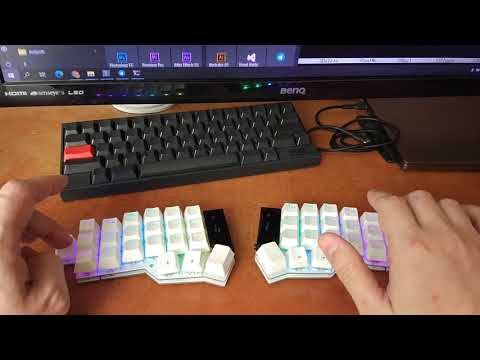
RGB is fully supported by ZMK now. Video:
You may use any addressable RGB leds, if you enable VCC control in firmware. There was an RGB leak issue in the earlier versions. Now all the latest nRFMicro releases have the output switch that cuts off external VCC so there's no leak anymore.
nRFMicro doesn't have the RGB leak issue anymore (software controlled EXT_GND since 1.0, EXT_VCC since 1.2).
The problem is that addressable RGB LEDs draw up to 1 mA each when off.
- https://cdn-shop.adafruit.com/product-files/1138/SK6812+LED+datasheet+.pdf (see "Static power consumption")
- https://www.pjrc.com/how-much-current-do-ws2812-neopixel-leds-really-use
Possible solutions would be desoldering ALL LEDs or cutting VCC line on the Corne/Helidox boards or/and adding a software-controllable switch to the power bus. The only source of power on the keyboard is the keyboard controller so if we disconnect VCC or GND pins internally, we completely prevent the battery leak. Historically there were two methods:
- ЕXT_VCC - software-controlled VCC output from the controller
- EXT_GND - software-controlled GND output from the controller
It's either EXT_VCC or EXT_GND, not both. Note keyswitch matrix works no matter what, because it's wired directly to gpio pins.
Some nRFMicros disable external VCC bus with a P-MOSFET. The 2M pull-down resistor keeps the switch open by default. There's a tradeoff in battery leak (I = 3.3V/2M = ~1.65 uA) vs mosfet opening time (t = 3nC/3.3V*2M = ~1800uS) for the 2M resistor.
You can keep LEDs turned off indefinitely and the keyboard matrix still works (it's connected to its own bus through the MCU). The GPIO state is retained in deep sleep mode so it's possible to keep the High state on the power pin even during a deep sleep, preserving the battery.
TL;DR: this switch works in reverse, high level on the POWER_PIN sets low level on EXT_VCC.

nRFMicro boards prior to 1.2 were cutting off external GND (not VCC). The schematic (taken from Hasu Alt controller) is somewhat flawed, it leaks current if the pin is not in the Hi-Z state (set the pin to input to save power). You can significantly reduce battery leak with 100K, 1M or even 2M resistor.
<Joric> hasuTMK, can you please elaborate about power control from Alt controller?
apparently when power pin is GND it leaks about 0.5 mA straight to the ground. or not?
how to make it battery friendly?
<Joric> people say 100K or even 1M will do, mosfet doesn't need much current
<Joric> i'm just wondering what were you thinking
<hasuTMK> It is just for sake of my assembly process. I also think you can use those values.
You can replace R = 10K with R = 2M (gate charge q = 3nС max, at Vgs = 4.5V). After that we get only 1.65uA leakage current (I = 3.3V/2M) with ~ 450uS mosfet opening time (t = q/I = 3nC/1.65uA).

Another possible solution is to use a single 3.3V or 5V LDO (Low Dropout Regulator) to control VCC output. There's EN pin on the regulator that enables output voltage at a logical High, so you get both regulated output and a trigger without pull-up resistors. The problem is to use it you would need a second LDO (or use an internal LDO if any) to power MCU separately.
You can use AP2112K-3.3-TRG1 in SOT-23-5 package, they cost just $6 for 100 pcs, or 6 cents a piece:
- https://www.aliexpress.com/item/32527338845.html (AP2112K-3.3, $6 for 100 pcs, marked 4A2D, probably XC6204)
You can also try adding power switching circuit to the keyboard. It could be problematic but possible to cut through the VCC line for the LEDs on the keyboard and to add a digital switch. You can cut off the OLED screen as well.
Circuitjs simulation for the power switch: https://tinyurl.com/t9ayker

The "Hasu scheme" (see HHKB_controller_revG.pdf) sets power pin (PORTD) to low to disable switchboard ("input with pull-up" is not related to the power switch, it's another circuit, matrix output, PORTB). See hhkb_avr.h. For the power switch we just set mosfet pin to High for ON and set it Low for OFF.
static inline void KEY_POWER_OFF(void) {
    /* input with pull-up consumes less than without it when pin is open. */
    DDRB = 0x00; PORTB = 0xFF;          // change pins input with pull-up
    DDRD |= (1<<4); PORTD &= ~(1<<4);   // MOS FET switch off
}
So the options are:
- Single N-MOSFET (Si2036) disconnects GND, usually there's no room for the second GND net.
- Single P-MOSFET (AO3047) disconnects VCC at 1, interferes with deep sleep on some MCUs
- Two mosfets and a resitor to model high-side switch with active-high enable pin.
- Solid state relay (also high-side switch with active-high enable pin).
- Voltage regulator and the EN pin (also high-side switch with active-high enable pin).
Possible 2 mosfet solution (LVCC is LED VCC line, digital POWER_PIN turns LVCC on with the logical 1):

Possible solid state relay solution in SOT-23-5: G5243A (Vanxy store).
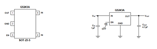
Wire POWER_PIN to EN, GND to GND, VCC to IN, LVCC to OUT. Capacitors are not necessary.
- G5243A substitutes (high-side switch with active-high enable pin): AP2821, RT9724.
- Other possible substitutes (different pinout): RT9711 NCP380 FP6861 RT9706 AAT4612 AAT4250 AAT4610 AAT4618 NCT3521U MIC5214 RT9702 PI5PD2051B, 41B PI5PD2061, 65 R5524N LN9701 AOZ1310 YF9001 SiP4610 AAT4614 R5523N SC1301A/B.
Possible LDO solution in SOT-23-5: AP2112K-3.3-TRG1, XC6220B331MR-G, generally all the LDO regulators with the EN pin.
Upd. Apparently diode is not responsible that much, see even I connect 1N5819W(SOD123) directly to these two pad, the board still hot while I turn on the RGB.
Schottky diode in the power selector circuit (1N5819 in SOD-323 package) is rated 350 mA, full LED matrix that can draw up to 900 mA (60 LEDs at 15 mA each) so it can lead to overheating of the diode (only when powered from USB). Most SOD-323 diodes seem to have 350 mA continiuous forward current. There are rare power diodes such as 0.5 mA B0540WS-7 or 3A BAT60B. Note that SOD-323F package is slighly better for SMD soldering (flatter) but it's hard to find.
- https://www.aliexpress.com/item/1005001498312983.html BAT60B diode, 1N5819 substitute (3A vs 350mA for RGB).
Note that in reality current may exceed 1A (USB 2.0 should be capped to 500 mA but really you can draw much more than that).
Even with 3A BAT60B you won't get rid of the overheating issue (checked with nRFMicro 1.4 and 28 LEDs, it's heating up pretty substantially). It's caused by the Schottky's voltage drop multiplied by the overall current consumed the by LEDs (with 8-10 LEDs it's barely noticeable). You may check for "ideal" (zero drop) diodes or try larger diodes with a better heat dissipation.
- https://www.analog.com/en/technical-articles/ideal-diode-controller-eliminates-energy-wasting-diodes-in-power-or-ing-applications.html
- https://www.ti.com/product/TPS2116#product-details
Increasing the copper area also could help significantly (SOD-323 pads are super-tiny so heat just cannot dissipate properly).
Here's how diode pads look in nRFMicro 1.4 (middle of the picture, pads 1 and 2). The size of those tiny pads actually made the layout possible becase I needed data vias around there. Resistors are so tightly packed you can't even put a trace between them.

All the traces in nRFMicro are 0.2 mm. If you go sub 0.2 this calculator might help:

Also see related issue here:
Also read the story about the old Elite-C thing, bad diode choice (good read):
- http://www.smdmark.com (probably the best SMD codes lookup site, in Chinese, understands ABx notation)
- http://caxapa.ru/codebook another SMD codes search
- Methods preventing reverse current in LDOs
- https://connectorbook.com/identification.html Connector identification chart