PCBA
Converting nRFMicro to a PCBA-frienly board will need some effort from your side, it's currently DIY handsoldering only. PCBA (Printed Circuit Board Assembly), or SMT (Surface Mount Technology) assembly is required for mass production. PCBA can be done by many fabs, the easiest to deal with are JLCPCB, Elecrow and PCBWay. This article covers a few PCBA issues.
- As of 2 May 2020 PCBA branch got too much attention and went closed source. Please make your own board.
- It needs quite a few iterations and months of time. Each iteration costed me around $50 (it's closer to $100 now).
- The great starting points would be Mikoto (4-layer nRF52840-based), IF-Nano (2-layer) and Osprey Keyboard (2-layer).
The cheapest factory for now is JLCPCB. Board size is 20x20mm minimum (Pro Micro is 18mm) so add tooling holes or panelize the board. They didn't solder USB connectors back then (now they do) so I used card edge PCB connector (try green mask for 0.8mm PCBs). Use nRF52840 in AQFN-73 package and small parts in 0402 packages. Use reference schematic from Nordic (e.g. rev. 5) with PCB antenna from nRF52840 dongle. Minumum cost is about $34 for 2 pcs and about $5 a board in larger batches (mostly because of nRF52840). I've used HASL, 2-layer board with 0.15 tolerance and 0.6 mm vias, so no added cost.
- 2021-01-28 This 1mm thick 2-layer HASL board fully built by JLCPCB via JLCPCB website (no e-mail interaction at all).

The "ears" are just to fit the minimal size requirement which is 20mm, they are also used as fiducials for SMT assembly.
First revision failed. One of the boards heated up, I've tried to resolder MCU but it was dead. Maybe needs ENIG for precision. The other board worked but didn't have radio (probably because I missed N24 cap and VSS_PA grounding).

I had to fix VSS_PA and N24 and redo MCU footprint. MCU cost skyrocketed so I decided to assemble the board at home.
- 2021-10-08 I've fixed the revision and got a stencil for it in a huge box but haven't tested it just yet. Unboxing video:

Comment,Designator,Footprint,LCSC Part
"100nF","C8,C9,C12,C13","Capacitor_SMD:C_0402_1005Metric","C1525"
"1uF","C14,C21","Capacitor_SMD:C_0402_1005Metric","C52923"
"1nF","C15","Capacitor_SMD:C_0402_1005Metric","C1523"
"100pF","C16","Capacitor_SMD:C_0402_1005Metric","C1546"
"1.5pF","C18","Capacitor_SMD:C_0402_1005Metric","C1552"
"1pF","C19,C20","Capacitor_SMD:C_0402_1005Metric","C1550"
"12pF","C1,C2,C3,C4","Capacitor_SMD:C_0402_1005Metric","C1547"
"4.7uF","C5,C6,C7,C11","Capacitor_SMD:C_0402_1005Metric","C23733"
"B5819W","D1","Diode_SMD:D_SOD-123","C8598"
"RED","D2","LED_SMD:LED_0603_1608Metric","C2286"
"BLUE","D3","LED_SMD:LED_0603_1608Metric","C72041"
"3.9 nH","L2","Inductor_SMD:L_0402_1005Metric","C14033"
"15nH","L3","Inductor_SMD:L_0402_1005Metric","C27143"
"10uH","L4","Inductor_SMD:L_0603_1608Metric"," C1035"
"AO3401A","Q1,Q2","Package_TO_SOT_SMD:SOT-23","C15127"
"100k","R1","Resistor_SMD:R_0402_1005Metric","C25741"
"0R","R10","Resistor_SMD:R_0402_1005Metric","C17168"
"5.1k","R2,R3","Resistor_SMD:R_0402_1005Metric","C25905"
"10k","R4","Resistor_SMD:R_0402_1005Metric","C25744"
"750k","R6","Resistor_SMD:R_0603_1608Metric","C23240"
"2M","R7,R9","Resistor_SMD:R_0603_1608Metric","C22976"
"1k","R5,R8","Resistor_SMD:R_0402_1005Metric","C11702"
"nRF52840","U1","Package_DFN_QFN:Nordic_AQFN-73-1EP_7x7mm_P0.5mm","C1851953"
"TP4054","U2","Package_TO_SOT_SMD:SOT-23-5","C32574"
"XC6206P332MR","U3","Package_TO_SOT_SMD:SOT-23","C5446"
"32MHz","Y1","Crystal:Crystal_SMD_2016-4Pin_2.0x1.6mm","C284175"
"32.768kHz","Y2","Crystal:Crystal_SMD_3215-2Pin_3.2x1.5mm","C32346"
- 2021-09-14 I'm trying the second version. Looks like components alone cost $40 for two boards (~$360 for 30 boards).
JLCPCB now costs way too much for prototyping. I'll try stencil and hotplate.
Aliexpress appear to have nRF52840 for $3 and BQ24075 for $0.62, even now, despite the global chip shortage.
- https://www.aliexpress.com/item/1005003006689926.html (nRF52840, $3, seller says it's brand new chips)
- https://www.aliexpress.com/item/1005002502927135.html (BQ24075, $0.62)
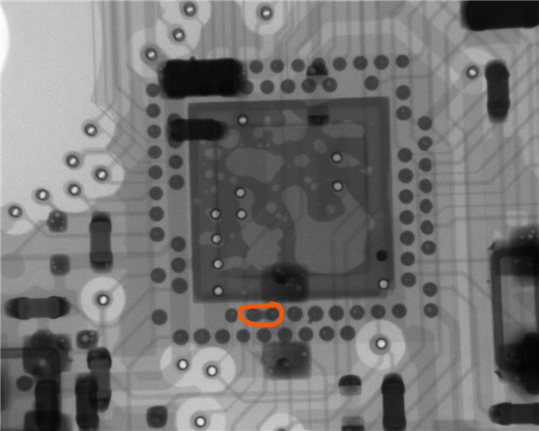
Aliexpress also has R7 MCU option (smaller rolls). Looks like nRF52840 R7 version (C1851953) is always cheaper (at least $5 cheaper). Also they don't add X-ray inspection for R7 (or maybe X-ray is optional now):

Both are sourced from LCSC apparently:

JLCPCB placement rendering ought to be better this time. I ditched PCB edge connector because they have midmount USB-C now.

Ordered nRFNano 2.0 from ALLPCB for free with coupons (normally it costs $5 for 20 boards and $13 for stencil + shipping ~ $39 total):


Got them in january 2022. Got all components from Aliexpress. Still couldn't find time to build and test them, too busy at work.
Comment,Designator,Footprint,LCSC Part
"100nF","C8,C9,C12,C13","Capacitor_SMD:C_0402_1005Metric","C1525"
"1uF","C5,C14,C21","Capacitor_SMD:C_0402_1005Metric","C52923"
"100pF","C16","Capacitor_SMD:C_0402_1005Metric","C1546"
"1nF","C17","Capacitor_SMD:C_0402_1005Metric","C1523"
"1.5pF","C18","Capacitor_SMD:C_0402_1005Metric","C1552"
"1pF","C19,C20","Capacitor_SMD:C_0402_1005Metric","C1550"
"47nF","C22","Capacitor_SMD:C_0603_1608Metric","C1622"
"10uF","C24","Capacitor_SMD:C_0603_1608Metric","C19702"
"12pF","C1,C2,C3,C4","Capacitor_SMD:C_0402_1005Metric","C1547"
"4.7uF","C6,C7,C10,C11,C15,C23,C25","Capacitor_SMD:C_0402_1005Metric","C23733"
"RED","D2","LED_SMD:LED_0603_1608Metric","C2286"
"BLUE","D3","LED_SMD:LED_0603_1608Metric","C72041"
"USB C","J1","Wireless-Parts:easyeda_C168688","C168688"
"3.9 nH","L2","Inductor_SMD:L_0402_1005Metric","C14033"
"15nH","L3","Inductor_SMD:L_0402_1005Metric","C27143"
"10uH","L1,L4","Inductor_SMD:L_0603_1608Metric"," C1035"
"100k","R1","Resistor_SMD:R_0402_1005Metric","C25741"
"0R","R10","Resistor_SMD:R_0402_1005Metric","C17168"
"5.1k","R2,R3","Resistor_SMD:R_0402_1005Metric","C25905"
"2k","R4","Resistor_SMD:R_0402_1005Metric","C4109"
"10k","R5,R11","Resistor_SMD:R_0402_1005Metric","C25744"
"1k","R8","Resistor_SMD:R_0402_1005Metric","C11702"
"10M","R9","Resistor_SMD:R_0402_1608Metric","C26082"
"nRF52840","U1","Package_DFN_QFN:Nordic_AQFN-73-1EP_7x7mm_P0.5mm","C190794"
"BQ24075","U2","Package_DFN_QFN:VQFN-16-1EP_3x3mm_P0.5mm_EP1.6x1.6mm","C15464"
"XC6220B331MR","U3","Package_TO_SOT_SMD:SOT-23-5","C86534"
"32MHz","Y1","Crystal:Crystal_SMD_2016-4Pin_2.0x1.6mm","C284175"
"32.768kHz","Y2","Crystal:Crystal_SMD_3215-2Pin_3.2x1.5mm","C32346"
Mikoto is an open-source (https://github.com/zhiayang/mikoto) alternative to nice!nano. See Alternatives#mikoto.

Check out the reduced size heatsink pad for the nRF52840. This design allows for more vias for the internal pins. Very clever.

Mikoto soldering video:

Note JLCPCB only solders their own components so you're limited to their inventory: https://jlcpcb.com/parts
- You can replace mosfets with SI2301CDS-T1-GE3 or any SOT-23 P-MOSFET.
- There are no 2M and 806K resistors in 0402 packages in the basic inventory. You can either use 750K+2M in 0603 packages or 470K+1M in 0402 packages (I used 0603 packages where needed).
- The BlueMicro840 build managed to have only two parts from the extended catalog: AP2112K and 806K resistor in 0603 package (if you go from 0603 to 0402 you will need more extended parts).
- You can try replacing 806K resistor with 750K from the basic catalog, the error is 6.25% from the ideal 800K one, and ADC will be capped at about 3.93V instead of 4.2V. You can't go up to 1M, because of 40us ADC acquisition time, see Batteries.
- It's probably possible to use 470K/1M divider using 0402 parts. The error would be about 15% (470K vs 400K) but considering voltage measurement isn't accurate anyway it'll do. You can also try 1M pull-down for the EXT_VCC mosfet.
- You can try replacing AP2112K with XC6220 (600 mA, QC 55uA vs 1A, QC 8uA so it's much better) from the extended catalog, looks like SOT25 and SOT-23-5 have precisely the same footprint (do not confuse with SOT-23-3 as in XC6206).
- You can replace AP2112 with XC6206 from the basic catalog if you CHANGE THE FOOTPRINT, because they are in different packages (SOT-23-5 vs SOT-23-3), if you ignore that, the pins don't line up. Also XC6206 is only 200 mA compared to 600 mA AP2112K so you won't be able to run per-key RGB LEDs.
Schematic is mostly taken from the reference layouts (I used ver. 5 with 3.3V external power, ver. 4 with High Voltage mode has SWD issues because of 1.8V core). I'm trying to use LCSC components only, so no prebuilt BT modules. PCB antenna is taken from nRF52840-Dongle Altium HW files.
I used rev. 5 with DCDC mode (not the high voltage mode, so no VDDH supply), because power consumption is like double without DCDC, and e73 uses it, see https://devzone.nordicsemi.com/nordic/power/w/opp/2/online-power-profiler-for-ble.
TL;DR: JLCPCB SMT assembly can't do much. Super limited inventory that you can't expand, so you have to choose carefully.
Considering sticking to the 2-layer board, minimum specifications are 0.127mm traces with 0.127 spacing. JLCPCB is a cheap fab house, and I wouldn't push the limits unless I need to, so I prefer using 0.15mm traces and 0.15mm spacing. Regarding vias, absolute minimum via size for the 2-layer board is 0.6 mm with 0.3mm via drill.
- 2021-08-19: There's a new R7 packaged nRF58240, part code C1851953 on lcsc (and surprisingly also on jlc) that's nrf52840 but cheaper. $7 per chip at quantities of 1-9. QIAA-R and QIAA-R7 are supposedly only packaging differences so idk what's going on here: https://jlcpcb.com/parts/componentSearch?isSearch=true&searchTxt=nrf52840 upd. This is referring to what kind of container the devices will be delivered in, 13" reel, 7" reel or tray, https://devzone.nordicsemi.com/f/nordic-q-a/33499/nordic-nrf52840-qiaa-r-or-r7 so they're the same just cheaper

- 5 Dec. 2020: they got nRF52840 MCUs in their extended inventory:

- 10 Dec. 2020: nRF52840 REMOVED.
- 11 Dec. 2020: nRF52840 ADDED back.
- 19 Dec. 2020: they got e73 nR52840 modules in their extended inventory (mostly out of stock):

- 24 Apr. 2021, naked nRF52840 started to cost crazy expensive due to shortage, $7 for small batches, $29 for 2 pcs.
| NRF52840-QIAA-R, 5 Dec 2020, JLCPCB | NRF52840-QIAA-R, 24 Apr 2021, JLCPCB |
|---|---|
 |
 |
- 6 Jul 2021, they cost $9.55 now and almost out of stock https://jlcpcb.com/parts/componentSearch?searchTxt=nrf52840

Note nRF52840 doesn't need in-pad-vias, just can short a few pads to route out reset, etc. (see nRF52840 dongle). I've managed to do that with 0.15 tracks, 0.15 spacing, 0.6 vias and 0.3 via drills.
You can route all the pins if you cut out the rectangle in the middle. it does nothing aside from heat dissipation, you can trim it substantially (don't forget to put 4x4 grid of ground vias to this polygon for better shielding/thermal mass).

More about aQFN-73 and its problems here (TL;DR some fabs, e.g. PCBWay require ENIG instead of HASL for those chips):
- Circuit Board Guidelines for aQFN Package
- There are no balls on the pins of the aQFN package, meaning it is more a LGA style than BGA style
- Nov. 2020: they started assembling boards with black mask, only green boards were available back then:

There's also a problem with 20x20 mm min size limitation (pro micro is 18 mm wide). You can try adding tooling holes, grouping two boards into one with mouse bites or use inhouse panelization by JLCPCB (see video about small boards): https://youtu.be/GpR87cdEdZc

- 2021-06-08: JLCPCB got midmount 14-pin connector C168689 https://jlcpcb.com/parts/componentSearch?isSearch=true&searchTxt=c168689
It's very similar to C168688, I think footrpints are compatible. This one is for 1.0 mm PCBs only.

- They also have real C168688 now https://jlcpcb.com/parts/componentSearch?isSearch=true&searchTxt=C168688

There were no connectors in the JLCPCB inventory. You could've tried PCB USB-C connectors library to make complete boards.
- https://www.40percent.club/2020/08/gherkin-express.html
- https://github.com/Pinuct/Eagle_PCB_USB_connectors
- https://www.snapeda.com/parts/add (eagle converter)
PCB connectors will work with 0.8 mm PCBs only (preferably even 0.7-0.6 mm). JLCPCB SMT only allowed >=1.0mm.
While 0.8mm is not ideal (0.7mm is better) it still works with standard USB-C connectors. 1.0 mm barely fits.
- See USB Type-C Specification Release 1.2.pdf, page 46:

USB-C leaf should be 0.70mm +/- 0.05 mm but 0.8mm is totally fine (I even managed to use 1.0mm PCBs).

- 10 Dec. 2020: they DON'T do 0.8 mm PCBs, only "1.0/1.2/1.6mm thickness and 1oz copper" so no PCB connectors.
- 12 Dec. 2020: got official reply about 0.8 mm pcbs from JLCPCB support Very sorry that we don't support 0.8mm PCB assembly at present. Since very few customer need this 0.8mm option, if we open it, there is no enough orders for panel production, it will cause very big production cost, so, we don't support 0.8mm assembly now, please kindly understand.
- 5 Jan. 2021: it's possible to order 0.8 mm PCBs for SMT assembly, green mask only (at least order form allows it).
- 24 May 2021: they officially support green 0.8 mm PCBs now, see https://cart.jlcpcb.com/quote:

You can also try combining footprints so you can just break the middle leaf off and solder midmount connector:

See Eagle USB-C library.
- 2020-02-02 JLCPCB added USB connectors to their library. Currently top mount only.

- 17 Apr. 2021: they got USB-C midmount connectors (TYPE-C-31-M-27): https://jlcpcb.com/parts/componentSearch?isSearch=true&searchTxt=TYPE-C-31-M-27 But they are 24-pin, not 12 so much harder to route on a small board.

It needs 1.6 mm PCB and it looks like this, it's not quite the 12-pin type I use, at all:

When asked for missing parts, JLCPCB answers:
"For the components that not in JLCPCB library, I am sorry that we don't support to assemble them. Maybe you can find replaceable parts in library, if there is no replaceable parts, eithter, then you only can make SMT order without the parts."
JLCPCB only does surface mount parts within a tiny subset of LCSC (only common and in-demand parts), they manage to hold fast turnaround and dirt cheap price by limiting the parts subset, but it's mostly for prototypes (not production) and you're expected to solder on missing parts. Benefit is dirt cheap assembly if you optimize for it but you'd have to solder missing parts yourself.
As to date there was only 689 Basic components in the JLCPCB library, their extended catalog (items marked as "Extended Part") is pretty expensive ($3 per every name) and also very limited.
See BlueMicro840 setup for JLCPCB (use BlueMicro840.csv and BlueMicro840-all-pos.csv as BOM and CPL).
- https://github.com/jpconstantineau/NRF52-Board/tree/master/BlueMicro840 (repository)
- https://store.jpconstantineau.com/#/group/bluemicro (prebuilt boards store)
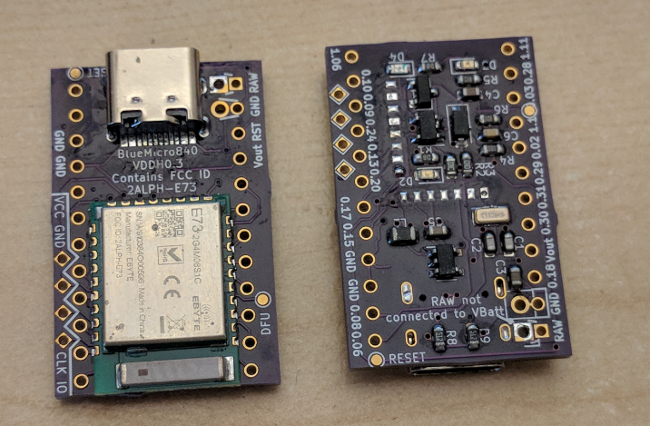
Bluemicro840 is double sided, one side is for SMT assembly the second is for module and connector (this is BlueMicro840 VDDH version 0.3 on the picture, but BlueMicro840 v1.x is about the same).
30 preassembled boards (except USB-C and E73 module) will cost about $54.95 plus shipping (E73 modules and top-mount USB-C from aliexpress will cost another $150 for 30 pcs)
This is for 30 pcs, including PCB cost, parts and assembly:

- https://jlcpcb.com/smt-assembly (JLCPCB SMT Assembly)
- https://youtu.be/GpR87cdEdZc (video about an example JLCPCB PCBA setup)
- https://jlcpcb.com/parts (JLCPCB parts catalog, different from LCSC)
- https://lcsc.com - LCSC inventory (thousands of parts, but unavailable for JLCPCB SMT)
- Green and black mask only, min size 20x20, Pro Micro is 33x18, had to add pieces on the sides
- They need "tooling holes" (managed to locate them outside of the board extended up to 20x20)
- No 0201 components at all, neither in Basic nor in Extended catalog, everything should be 0402+
- Mosfets are SOT23-5 only, no smaller ones
- Chargers are sot23-5 only, TP4054 is basic (not sure if suitable), mcp73871 is extended
- No nRF52840 (even nRF52832 that I cannot use is in extended catalog and out of stock)
Extended parts (EVERY extended part adds $3 to the total price of the SMT assembly):
- 4M resistor only in Extended, 4.7M is basic and 0603 only, 5.1M is extended, all 0402
- 820pF is only extended, 1nF is basic, 12pF is 0402 only, no 0.8pF, only 1pF.
- 0.5 pf is extended (1pF is basic), 32Mhz resonator is extended ONLY
Screenshot (pricing is for 5 assembled boards total, no shipping included):

The above setup is not working, saved for history only.
Along with the gerbers you also need bill of materials (BOM) and a component placement list (CPL). I'm using KiCad scripts, but you still need to check for the proper rotation (JLCPCB rotation doesn't always match KiCad, i.e. nRF52840 may be rotated 90):
Bill of materials, see "File" - "Fabrication Outputs" - "BOM file..." in Pcbnew (Kicad).
Comment,Designator,Footprint
"12pF","C1,C2","0201_C"
"0.8pF","C3","0201_C"
"0.5pF","C4","0201_C"
...
Component placement list, "File" - "Fabrication Outputs" - "Footprint position (pos) file..." in Pcbnew.
Designator,MidX,MidY,Layer,Rotation
C1,30.212,-44.708,top,180
C2,30.4,-40.644,top,0
C3,25.955,-42.676,top,0
...
Sourcing from LCSC and assembly in small batches would cost about $23 per board at 5 pcs. Assembly cost scales really well from there: PCBs and assembly cost $4 at 100 pcs, $2.3 at 200 pcs, $1.13 at 1000pcs. The most expensive part is parts cost, especially nRF52840 ($3.50 on average), so completed boards cost maybe $6-$8 total in large batches. You can also get components from other suppliers, see Consigned/kitted, Turn-key and Partial Turn-key/Combo options.
- https://github.com/ai03-2725/Unified-Daughterboard (Elecrow example setup)
Not checked, it could be $100 at small batches but it scales maybe down to $15 (can't really compete with PCBWay until getting into the 1000s). From June 1st 2020, they offer a 20%-50% discount for the PCB assembly cost.
If you're designing a PCB antenna this is your bible (please read):
Basic commandments:
- Remember the keepout area, to keep it holy.
- Honour thy 50 Ohm impedance matching trace.
- Thou shalt place components directly on the impedance matching trace with no stubs.
- Thou shalt keep VSS_PA capacitor separate from the common ground plane.
- Thou shalt have vias for every ground pin of the remaining capacitors of the RF block.
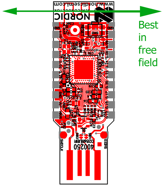
Antennas usually want unobstructed sides but we can't just provide that for the Pro Micro footprint. Luckily the antenna is omnidirectional, but the Pro Micro headers sure mess it up.
See https://devzone.nordicsemi.com/f/nordic-q-a/38418/nrf52840-dongle-antenna-characteristics:
Tracks on the PCB for the PCB antennas (and even chip antennas) should be carefully calculated and checked before putting in production. Ceramic antennas (chip antennas) are usually worse - they're smaller, have lower db than PCB antennas and have the same strict clearance requirements.
RF circuit usually includes 0 ohms resistor that can be changed later, the 50 ohms impedance matching trace (important!) and a capacitor before exiting the GND plane area (top and bottom GND planes should be really well connected with vias, add more GND vias, especially under the MCU, every capacitor need a separate via near the ground pin).
Impedance matching trace from nice!nano 1.0:

There's a PCB calculator built in the Kicad launcher:

Apparently the 50 ohm track should be 1mm wide with 0.2 mm gap, length doesn't really matter much.
Alternatives:
- AppCad: http://www.hp.woodshot.com (see "Coplanar Waveguide" for the 50 ohms track)
- Saturn PCB design: https://saturnpcb.com/pcb_toolkit ("Conductor Impedance", haven't used)
See Nordic USB dongle schematic (N.C. means Not Connected, this part is optional for tuning):

PCB (from the Nordic USB dongle schematic):

You can download PDFs and Altium design files here (use altium2kicad for conversion):
Impedance matching trace and antenna example (from the Nordic Dongle altium files):

Note the C3 capacitor should be connected separately from the common ground to enable harmonic filtering, use keepout area to keep it off the common GND plane.

I don't know how that matters, but it is somehow important. Note it's still connected to the heatsink GND plane but only to it:

See nRF52840 datasheet, page 542:

It would seem you'd have to go beyond 0.15 tolerance to layout the RF block properly. I tried to connect C3 via ground plane but apparently it might not work. Figures it could be routed with 0.15 tracks, 0.15 spacing if you move side pins just 0.00625 mm apart:

SMA socket (or rather, U.FL or IPEX connector) placement example (from the Nordic DC):

Note the SMA connector on the picture (MM8130-2600) has a built in switch that disconnects the PCB antenna when the external antenna is plugged in. Closeup:

DK uses a straight monopole antenna instead of the meander one, more info:
- https://infocenter.nordicsemi.com/pdf/nwp_008.pdf (printed monopole antennas)
Video on designing a PCB antenna:

(At 34:02 a Nordic employee recommends including a 50 ohm transmission line instead of matching the chip output directly to the antenna.)
-
BlueNano (832 chip) antenna is based on the TI Aplication note 43 (it's similar to the nordic one but has a clear grounding point): http://www.ti.com/lit/an/swra117d/swra117d.pdf
-
Another similar project, TinyPICO (https://www.tinypico.com) uses 3D antenna (proant 440). It's absurdly large but has 75% efficiency (PCB antennas barely do 50%, ceramic antennas are even worse).

JLCPCB SMT uses their own inventory (NOT LCSC), so the absolute majority of LCSC catalog is unavailable for JLCPCB soldering. It's possible, however to use Elecrow or PCBWay SMT soldering services and source parts from LCSC.
Example LCSC components for PCBWay sourcing. Prices are for 10+ units. Most SMDs are 0201, large capacitors are 0402:
| ID | LCSC PN | Price | Qt | Mfr.Part | Package | Description |
|---|---|---|---|---|---|---|
| U1 | C190794 | $4.41 | 1 | NRF52840-QIAA-R | AQFN-73 | nRF52840 |
| J1 | C168688 | $0.31 | 1 | USB-C SMD 16 pin | SMD | Midmount USB-C |
| Q1 | C461063 | $0.14 | 1 | DMP2088LCP3-7 | X2-DSN1006-3 | P Channel MOSFET |
| Q2 | C443826 | $0.14 | 1 | DMN3110LCP3-7 | X2-DSN1006-3 | N Channel MOSFET |
| D1 | C478156 | $0.14 | 1 | PMEG4010ESB | DSN1006-2 | Schottky diode |
| X1 | C341819 | $0.14 | 1 | XRCGB32M000 | SMD-2016_4P | 32MHz Resonator |
| X2 | C99009 | $0.15 | 1 | 7PF20PPM | SMD-2012_2P | 32.768KHz Crystal |
- You can also use look for MOSFETs in SOT-883 packages, e.g. LP0404N3T5G, they're pretty small.
- Also, add a fuse protection, maybe (the board is pretty much out of free space already).
-
Symmetry Electronics has nRF52840-QIAA in stock (starting from $3.49).
-
Also the new nRF52833 came out and it looks to be super similar to nrf52840 in features with half the ram, half the flash, but a pretty cheap price ($3.32). It also has Bluetooth 5.2 direction finding.
-
nRF52840 QIAA costed just 14.80 CNY (~ $2.07) on Taobao.
-
Alibaba.com (kinda like taobao for suppliers) do have some of these for fairly reasonable prices. But the downside is you gotta message/chat with them for a quote (larger suppliers are more responsive from my experience).
-
Alibaba sells E73s for $4.56 (100-499 pcs): https://www.alibaba.com/product-detail/small-size-integrated-ARM-MCU-wireless_62096319088.html
-
Alibaba also sells NRF52480 (I'm assuming highest price would be around $2.86, although it doesn't get much better until you get into the 10000s): https://www.alibaba.com/product-detail/-Bluetooth-Module-NRF52840_62403034094.html

- Winsource quoted nRF52840-QIAA-R $2.65 for 19+ pcs, but I haven't checked the reliability of this source: https://www.win-source.net/search?q=nrf52840
- https://jlcpcb.com/smt-assembly
- https://jlcpcb.com/client/index.html#/parts/
- https://github.com/ai03-2725/Unified-Daughterboard
- https://github.com/jpconstantineau/NRF52-Board/
- http://infocenter.nordicsemi.com/pdf/nRF52840-QIAA_Ref_Layout_v0.5.zip
- https://www.nordicsemi.com/Software-and-Tools/Development-Kits/nRF52840-Dongle
- https://devzone.nordicsemi.com/f/nordic-q-a/38418/nrf52840-dongle-antenna-characteristics
- https://devzone.nordicsemi.com/nordic/nordic-blog/b/blog/posts/measuring-lithium-battery-voltage-with-nrf52
- https://devzone.nordicsemi.com/f/nordic-q-a/16589/nrf52-output-impedance-clarification