The Mandelbrot Set is a product of IBM research scientist Benoit Mandelbrot’s work in the 1970s and 1980s. Mandelbrot was tasked to investigate into the reduction of white noise that disturbed transmission lines. When he began his investigation he took it upon him self to visualize the data, and the results showed a structure with self-similarity at all scales. This structure is known as the fractal. There are many sorts of fractals, but what they all have in common are that they show signs of self-similarity. Self-similarity means that if you had to zoom into a fractal you would notice that patterns repeat themselves. A particular fractal was labelled as the Mandelbrot set as shown in the animation below:
Using an FPGA, hardware can be designed to optimize the Mandelbrot set calculation. Due to the intensive calculations required to continuously update the set, as a result of zooming and panning the image, a parallel implementation can drastically improve the computation time. The course grained nature of the operation leads towards a distributed memory approach. Although there is a communication overhead and synchronization cost, the parallelized implementation can leadto an accelerated computation time which is faster than other standard processing platforms.
The Button Driver poles the Buttons and Switch values and sends a panned x, y shift as well as a zoom factor Z to the Mandelbrot Module. Each button press is debounced to ensure a single press doesn’t appear like multiple presses. The zoom factor increments in steps of 5. The values of x and y are also divided through by z before being outputted to ensure adequate scaling of the pan.
The Mandelbrot Module takes each pixel and assigns it a corresponding complex number using the scaling factor and the pan specified by Button Driver. This complex number is used to calculate the corresponding pixel value. If the corresponding complex number is not in the set the pixel value is set to its respective colour based on the number of iterations it took to prove so.
The memory used is a true dual port RAM block. It has simultaneous read and write functionality provided we do not read from, and write to the same address at the same time. The input address is specified by the Mandelbrot Module whereas the output address is specified by the Engine Module.
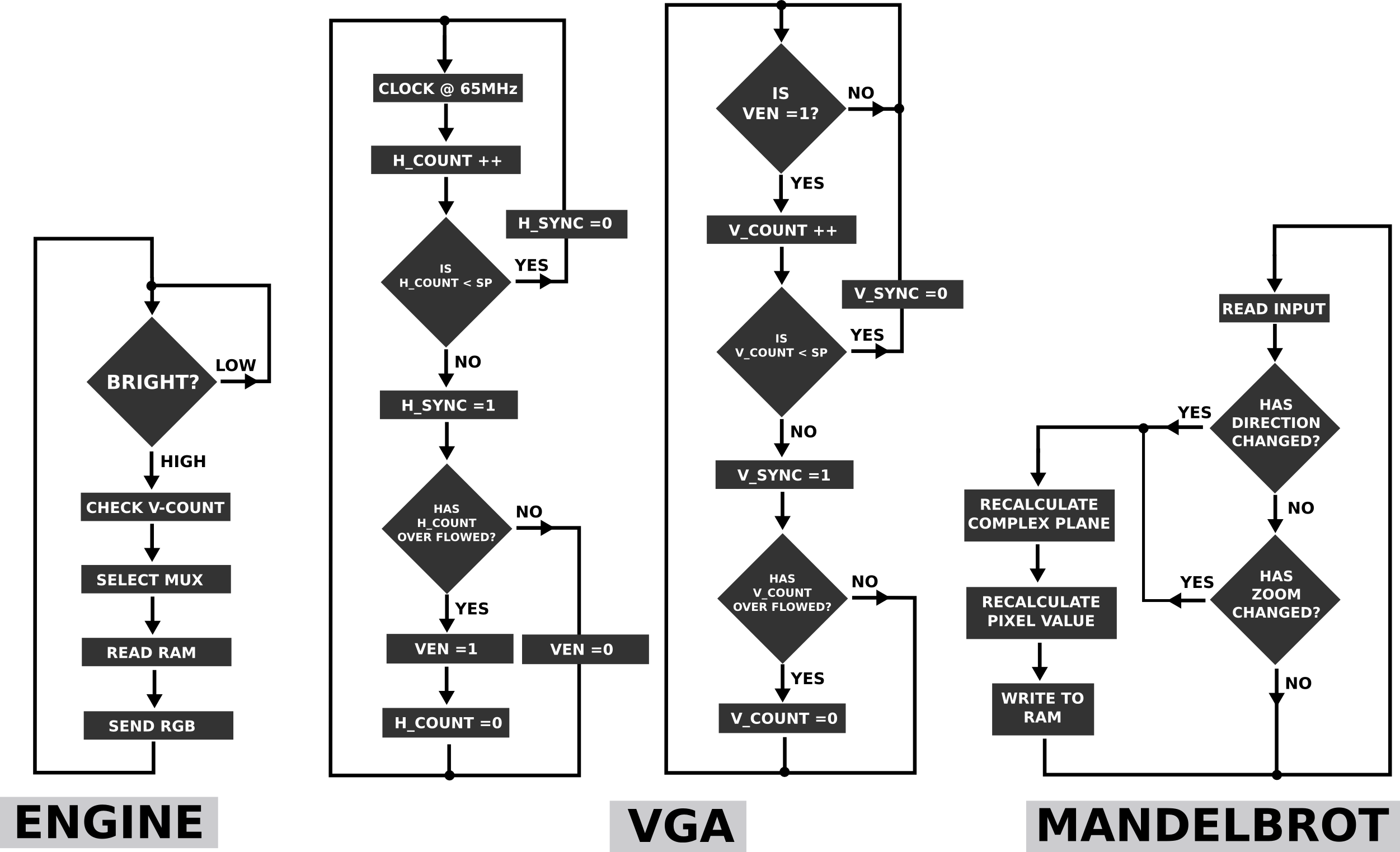
The Engine Module is clocked at a speed of 65MHz, this produces a frame refresh rate of 60Hz. The Engine reads from a RAM block only when the bright bit from the VGA driver has been set. An address counter (reset to zero for each RAM Block) is used to increment through the addresses of each block of memory. The corresponding output data is written to the screen. Once a single RAM Block has been read a RAM counter is incremented. This happens when vcount is equal to 48 when the screen resolution is 1024x768 and there are 16 blocks of memory. This RAM counter then is used to selected the corresponding multiplexer input.
The VGA driver will drive the VGA display using 2 control signals (which are normally high), the horizontal synchronization (hsync) and the vertical synchronization (vsync). It also provides the engine with the bright signal which will be high when the engine needs to output the RGB pixel data. The clock rate (pixel clock) at which the driver operates is the amount of time to display one pixel of information.
The control signals are used by the monitor as follows. When hsync is pulsed low, it tells the monitor to start scanning at the beginning of the next row of pixels. When vsync is pulled low, it tells the monitor to return to the beginning of the image, i.e. to start a new frame. These signals are used to co-ordinate the delivery of the RGB data to the correct pixel on the screen.
To know when to pulse hsync and vsync, two counters (hcount and vcount) are employed to count the ticks of the pixel clock. Both counters are assigned an overflow value that if reached will reset the counters to zero.
Hcount will increment with each tick of the pixel clock, with its overflow value depending on how many pixels are required for the horizontal dimension of the frame. Each time hcount is reset, hsync will be pulled low for the duration of a sync pulse, SP. Hsync will then go high for a small blanking time called the front porch (FP). After the front porch, hsync remains high as the monitor will now be outputting pixels onto the screen. Once the row has been scanned, hsync remains high as another blanking time is required, called the back porch (BP). After the back porch, Hcount is reset and Vcount is incremented by pulsing an internal bit (ven) from low to high which will increment Vcount.
Vcount will only increment if ven is high. Vcount follows the same procedure as hcount, in that it also has a sync pulse, a front porch and a back porch. The overflow value of vcount depends on how many rows of pixels are required for the vertical dimension of the frame and vcount are within the addressable region. The value of vcount is also output to the Engine module for the memory addressing process.
This FPGA based project done for digital systems course at The University of Cape Town, by: Misha Mesarcik Brandon Joffe Jonathan Malin


