This repository will actually serve as a aid to help you get started with your own template. You should copy the raw form of this readme into your own, and use this template to write your own. If you want to draw inspiration from other classmates, feel free to check this directory of all students!.
- Table of Contents
- Hello_CircuitPython
- CircuitPython_Servo
- CircuitPython_LCD
- Tempature Sensor
- RotaryEncoder
- Photointerrupter
For this assignment we had to learn vscode and we made a button blink red
Here's how you make code look like code:
Code goes here
import board
import neopixel
import time
dot = neopixel.NeoPixel(board.NEOPIXEL, 1)
dot.brightness = 0.5

print("Make it red!")

while True:
    dot.fill((255, 0, 0))
    print("Red")
    time.sleep(0.5)

    dot.fill((255, 0, 255))
    print("Purple")
time.sleep(0.5)t-5rQwrZyxD5Dfk3fN3EBfTk3tWPozGAF2.mp4
And here is how you should give image credit to someone, if you use their work:
Image credit goes to matthias
https://www.tinkercad.com/things/l74pWa2Bojx-brave-turing/editel?tenant=circuits
I got some help from Mr H in order to learn python and vscode. I also forgot to have the library and you should remember to insert the library for neopixel.
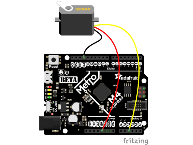
this assignment we were asked to move a servo 180 degrees
Code goes here
# SPDX-FileCopyrightText: 2018 Kattni Rembor for Adafruit Industries
#
# SPDX-License-Identifier: MIT

"""CircuitPython Essentials Servo standard servo example"""
import time
import board
import pwmio
from adafruit_motor import servo

# create a PWMOut object on Pin A2.
pwm = pwmio.PWMOut(board.D7, duty_cycle=2 ** 15, frequency=50)

# Create a servo object, my_servo.
my_servo = servo.Servo(pwm)

while True:
    for angle in range(0, 180, 5):  # 0 - 180 degrees, 5 degrees at a time.
        my_servo.angle = angle
        time.sleep(0.05)
    for angle in range(180, 0, -5): # 180 - 0 degrees, 5 degrees at a time.
        my_servo.angle = angle
time.sleep(0.05)SERVO.mp4
 Kattni Rembor, Jeff Epler, Carter Nelson, lady ada
it was a lot more challenging to use a servo because I had to rememeber how to wire and use a servo but google was my friend. Again, make sure you have the correct libraries for servos in there. Additionally, having it go 5 degrees at a time is crucial.
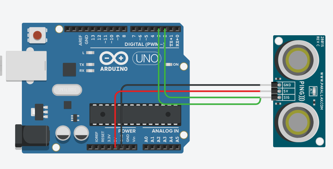
we had to make an ultrasonic sensor that faded the color of the board LED
#thanks graham, grant, and mason for the code
import time
import board
import adafruit_hcsr04
import neopixel
import simpleio

sonar = adafruit_hcsr04.HCSR04(trigger_pin=board.D3, echo_pin=board.D2)
matthias = neopixel.NeoPixel(board.NEOPIXEL, 1)#connecting the neopixel on the board to the code
matthias.brightness = .3  #setting the brightness of the light, from 0-1 brightness

while True:
    try:
        cm = sonar.distance
        simpleio.map_range(cm, 0, 20, 3, 20)
        print((sonar.distance))
        if cm < 7.5:
            red = simpleio.map_range(cm, 0, 6.5, 255, 0)# mapping the colors to the length
            green = simpleio.map_range(cm, 5, 7.5, 0, 230)
            matthias.fill((red, green, 0))
        if cm > 7.5 and cm < 12.5:
            green = simpleio.map_range(cm, 7.5, 10, 255, 0)
            blue = simpleio.map_range(cm, 9, 12.5, 0, 230)
            matthias.fill((0, green, blue))
        if cm > 12.5 and cm < 17.5:
            blue = simpleio.map_range(cm, 12.5, 15, 255, 0)
            red = simpleio.map_range(cm, 14, 17.5, 0, 240)
            matthias.fill((red, 0, blue))
        time.sleep(0.01)
    except RuntimeError:
        print("Retrying!")
    time.sleep(0.1)

### Evidence
Ultrasonic.mp4
And here is how you should give image credit to someone, if you use their work:
Image credit goes to matthias
 elias https://github.com/egarcia28/CircuitPython
this assignment was difficult because of the fading of the light and finding the right fade. the colors also have to be right if you want to make a rainbow. Using map functions may be difficult but it makes everything a lot smoother.
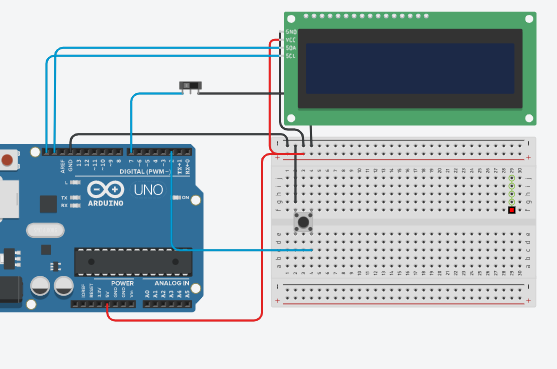
Using an LCD screen to count the number of times a button has been pressed. wiring up the LCD right is important and there are websites to help you. Additionally, debouncing the button gets the click # right.
Code goes here
Grant Gastinger https://github.com/ggastin30/CPython
Import necessary libraries
import board
from lcd.lcd import LCD
from lcd.i2c_pcf8574_interface import I2CPCF8574Interface
import time
from digitalio import DigitalInOut, Direction, Pull

Initialize input/output pins and variables
i2c = board.I2C() # Create an I2C object
btn = DigitalInOut(board.D2) # Initialize the button
btn.direction = Direction.INPUT
btn.pull = Pull.UP
clickCount = 0 # Initialize the click count to 0

switch = DigitalInOut(board.D7) # Initialize the switch
switch.direction = Direction.INPUT
switch.pull = Pull.UP

Initialize LCD object and display name
lcd = LCD(I2CPCF8574Interface(i2c, 0x27), num_rows=2, num_cols=16)
lcd.print("Matthias")

Main loop
while True:
if not switch.value: # Check if the switch is flipped
if not btn.value: # Check if the button is pressed
lcd.clear() # Clear the screen
lcd.set_cursor_pos(0, 0) # Set the cursor to the top left corner
lcd.print("Click Count:") # Print the title
lcd.set_cursor_pos(0,13) # Set the cursor to the 14th position on the first row
clickCount = clickCount + 1 # Increment click count
lcd.print(str(clickCount)) # Print the updated click count
else:
pass
else:
if not btn.value: # Check if the button is pressed
lcd.clear() # Clear the screen
lcd.set_cursor_pos(0, 0) # Set the cursor to the top left corner
lcd.print("Click Count:") # Print the title
lcd.set_cursor_pos(0,13) # Set the cursor to the 14th position on the first row
clickCount = clickCount - 1 # Decrement click count
lcd.print(str(clickCount)) # Print the updated click count
else:
pass
time.sleep(0.1) # Sleep for debounce. This is to make sure we don't register multiple clicks.WIN_20220927_10_20_59_Pro.mp4
 ###thanks elias https://github.com/egarcia28/CircuitPython
this was by far the hardest assignment but I had done something like this last year and my prior knowledge along with the help of classmates gave me what I needed to understand and complete the assignment. Make sure you have LCD library. Having the position of where it started was just as important. Along with the debounce and the time.sleep which made it easy to only register 1 click.
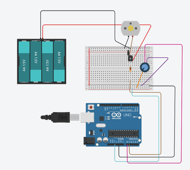
we had to make a potentiometer control a DC motor while using a battery pack.
Code goes here
#thanks https://github.com/willhunt914
#thanks https://github.com/nbednar2929
import board #import files
import time
from analogio import AnalogOut, AnalogIn
import simpleio

motor = AnalogOut(board.A1) #motor ouput
ptmr = AnalogIn(board.A0) #potentiometer input

while True:
    print(simpleio.map_range(ptmr.value, 96, 65520, 0, 65535)) #print my potentiometer value
    motor.value = int(simpleio.map_range(ptmr.value, 96, 65520, 0, 65535)) #push potentiometer value to motor
time.sleep(.1) #print delay WIN_20221109_09_51_31_Pro.mp4
 https://github.com/willhunt914/CirclePython#Moter_Control
make sure you] double checking your wiring before you plug in the bateries so you dont fry anything or have magic smoke. For the diodes the power flows in the direction of the silver cap. For the transistor, facing the flat side the power flows from left to right. remember to connect the gnd with a wire
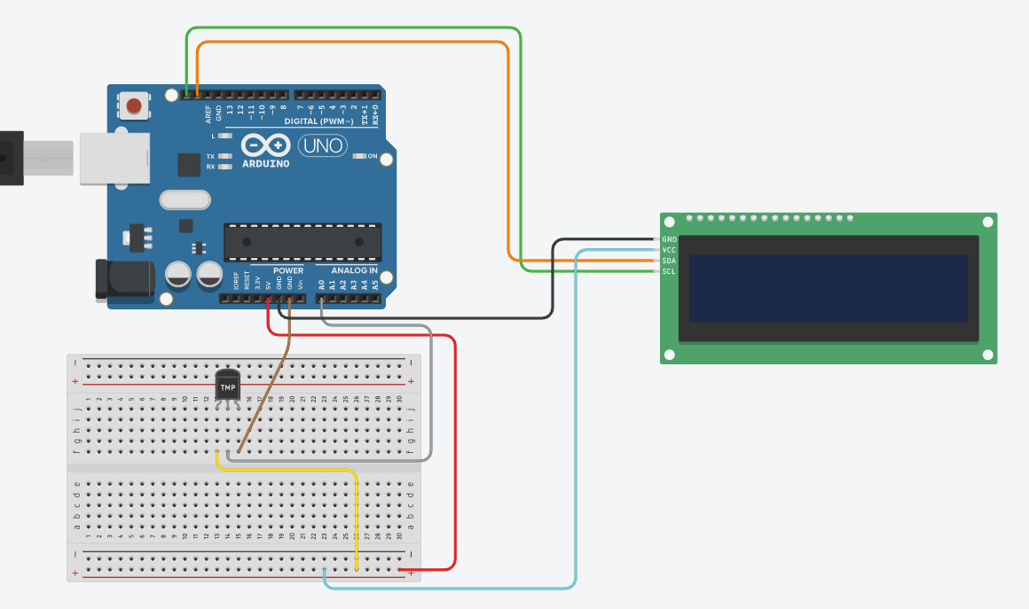
we had to use a tempature sensor and an LCD to display it.
Code goes here
#code from wmorela54
import board
import analogio
import time
from lcd.lcd import LCD
from lcd.i2c_pcf8574_interface import I2CPCF8574Interface


TMP36_PIN = board.A0  # Analog input connected to TMP36 output.

i2c = board.I2C()
lcd = LCD(I2CPCF8574Interface(i2c, 0x27), num_rows=2, num_cols=16) #0x27 or 0x3f

# Function to simplify the math of reading the temperature.
def tmp36_temperature_C(analogin):
    millivolts = analogin.value * (analogin.reference_voltage * 1000 / 65535)
    return (millivolts - 500) / 10

# Create TMP36 analog input.
tmp36 = analogio.AnalogIn(TMP36_PIN)
desired_temp_min = 70
desired_temp_max = 78

while True:
    # Read the temperature in Celsius.
    temp_C = tmp36_temperature_C(tmp36)
    # Convert to Fahrenheit.
    temp_F = (temp_C * 9/5) + 32
    # Print out the value and delay a  few seconds before looping again.
    print("Temperature: {}C {}F".format(temp_C, temp_F))
    time.sleep(3.0)
    if temp_F >= desired_temp_min and temp_F <= desired_temp_max:
        lcd.clear()
        lcd.print("It feels great  in here")
    if temp_F < desired_temp_min:
        lcd.clear()
        lcd.print("brrr too cold")
    if temp_F > desired_temp_max:
        lcd.clear()
        lcd.print("To hot")
time.sleep(2.0)F597015B-D1D7-4028-9CE3-8E79A38484E7.mov
 (credit cooper)
this was difficult until my bestfriend cooper let me borrow his code and wiring and video and that made it a whole lot easier. Having different points makes it easier to find a error or to see tempature. The delay is just as important and helps you get good readings.
For this assignment we were told to use a rotary encoder which when integrated with an LCD screen and LED's act as a traffic light. The rotary encoder code facilitates color changes in response to its rotation. By assigning specific color values to different encoder movements, each rotation triggers a smooth transition between colors, providing an interactive visual experience.
Code goes here
##thanks river! https://github.com/rivques/CircuitPython
import rotaryio  # Rotary encoder module
import board  # Board pin definitions
import digitalio  # Digital input/output module
import neopixel  # NeoPixel LED module
from lcd.lcd import LCD  # LCD module
from lcd.i2c_pcf8574_interface import I2CPCF8574Interface  # I2C interface for LCD

i2c = board.I2C()  # I2C object

# LCD initialization
lcd = LCD(I2CPCF8574Interface(i2c, 0x27), num_rows=2, num_cols=16)

led: neopixel.NeoPixel = neopixel.NeoPixel(board.NEOPIXEL, 1)  # NeoPixel LED initialization
print("neopixel")  # Print initialization message

led.brightness = 0.1  # Set NeoPixel LED brightness

button = digitalio.DigitalInOut(board.D12)  # Button pin initialization
button.direction = digitalio.Direction.INPUT  # Button pin set as input
button.pull = digitalio.Pull.UP  # Enable pull-up resistor for the button

colors = [("stop", (255, 0, 0)), ("caution", (128, 128, 0)), ("go", (0, 255, 0))]  # Color mapping

encoder = rotaryio.IncrementalEncoder(board.D10, board.D9, 2)  # Rotary encoder initialization
last_position = None  # Last encoder position variable

while True:
    position = encoder.position  # Current encoder position

    if last_position is None or position != last_position:
        lcd.clear()  # Clear LCD screen
        lcd.print(colors[position % len(colors)][0])  # Print label on LCD

    if not button.value:
        led[0] = colors[position % len(colors)][1]  # Set NeoPixel LED color

last_position = position # Update last position variablehttps://rivques.github.io/docs/trafficlight.gif link to a working video from river (mine wouldn't fit)

This assignment was very difficult for me and so I ended up using rivers code to help me with the assignment. The rotary encoder code enables the light to change colors based on the rotation of the encoder. By mapping the encoder's movements to different color values, each rotation triggers a color transition. this, combined with utilizing the LCD to see where I was made it easier. One challenge faced during development was an incorrect I2C address assumption for the LCD module. The code initially used an address of 0x27, but the module's actual address was 0x3F. This caused communication errors and prevented the LCD from displaying correctly. The issue was resolved by correcting the I2C address in the code, ensuring proper communication and LCD functionality.
Use a photinerrupter and track the amount of interrupts on an LCD screen.
Code goes here
import time #imports
import rotaryio
import board
from lcd.lcd import LCD
from lcd.i2c_pcf8574_interface import I2CPCF8574Interface
from digitalio import DigitalInOut, Direction, Pull

i2c = board.I2C()
lcd = LCD(I2CPCF8574Interface(i2c, 0x27), num_rows=2, num_cols=16) #identify LCD screen

photoint = DigitalInOut(board.D7) #identify photointerrupter
photoint.pull =Pull.UP #pull up photointerrupter
counter = 0 #create counter set to zero

while True:
    if photoint.value == True: #if photointerrupter
        counter = counter + 1 #add to counter
        lcd.clear()
        lcd.color = [0, 100, 0]
        lcd.set_cursor_pos(0, 0) #set lcd cursor position
        lcd.print("Interrupts:" + str(counter)) #print interrupts and counter on lcd
        time.sleep(.5) #0.5sec delay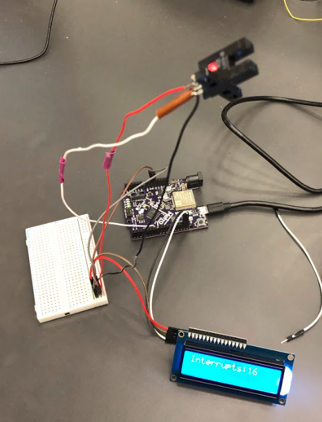
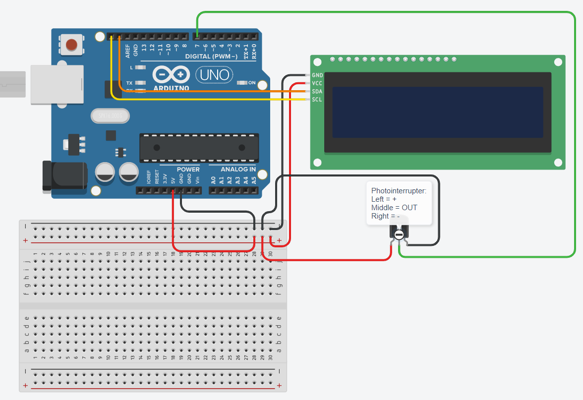
Thanks nick bendar for help with the wiring and the code. The code implemented a counter that incremented each time the photointerrupter's beam was interrupted by a piece of paper. The count was then displayed on an LCD screen, providing a real-time visual representation of the number of interruptions, allowing for convenient monitoring and tracking. It was important to set the LCD screen in the right place so that it starts on the left or so you can see it at all!
Code goes here