-
Notifications
You must be signed in to change notification settings - Fork 2
Home
Imagine a small device which monitors your balance, position, and take note of bumps and hits. If it detects a frightful circumstance it calls for help!
You can build this awesome futuristic guardian by yourself, following this simple guide.
Here is a list of the material you need for this project. Then you’ll find instructions to create your own watch case with a 3D printer.
- Xadow GSM+BLE w/ antenna http://wiki.seeed.cc/Xadow_GSMPlusBLE/
- Xadow 1.54” Touchscreen http://wiki.seeed.cc/Xadow_1.54_inch_Touchscreen/
- Xadow Audio http://wiki.seeed.cc/Xadow_Audio/
- Xadow GPSv2 http://wiki.seeed.cc/Xadow_GPS_V2/
- Xadow Basic Sensors http://wiki.seeed.cc/Xadow_Basic_Sensors/
- LiPo battery 520mAh (or higher...) https://www.sparkfun.com/products/13854
Install last version of Arduino from Arduino website www.arduino.cc. An old version should work too.
After installing Arduino open it, go in the “Preferences” window, copy this link: “https://raw.githubusercontent.com/Seeed-Studio/Seeed_Platform/master/package_seeeduino_boards_index.json” and paste it in the “Additional Boards Manager URL” form in Arduino settings.
Then go on Tools->Board->Boards Manager... and select “RePhone MT2502”
Type “rephone” And choose the one with MT2502 chip, which is the same of your rephone (you should read it on the IC).
Go back on Tools->Boards and now choose the Rephone board from the last positions of the list
Install the MTK Driver attached in the .ZIP file. Then connect the battery to your rephone, turn it on, and connect it to your computer with the USB cable. You should see COM ports in device manager of your Windows. If something doesn’t work, look for the solution following the steps on this Seeed page: http://wiki.seeed.cc/Arduino_IDE_for_RePhone_Kit/
You need now to install the firmware on your RePhone, so to use the Arduino IDE. Disconnect your RePhone from the PC and turn it off (press and hold the power button). Extract the .ZIP file and run FirmwareUpdater.exe, be sure the selected platform is “RePhone” (if not, click “Others” and locate firmware\LinkIt_Device\RePhone\W15.19.p2-uart\SEEED02A_DEMO_BB.cfg ) then click the big green button (which is for “downoad”).
Now you will be asked to connect your RePhone to PC via USB cable, make sure your RePhone has been turned OFF and a functional battery is powering the device. Wait until the downloading finishes. This might take about one minute, so it may remain stuck at 50% for quite a while, please be patient. In the Complete page click OK to finish the firmware update. If something goes wrong or if you need more details follow instructions on http://wiki.seeed.cc/Arduino_IDE_for_RePhone_Kit/
It’s time to test your RePhone with the usual “Hello World!” code. Press and hold the power key for 2 seconds to turn on the device (LED indicator shows GREEN). In the Windows Device Manager you see the COM ports as before, MTK USB Debug Port is used for uploading code, MTK USB Modem Port is used for logs, like printing messages in the serial monitor with Serial.println().
On the Arduino IDE window, click Tool => Port, select MTK USB Debug Port, which is in our case number 13, but you could have a different port.
Now copy the following code to your Arduino IDE:
// hello world for test RePhone
// loovee@10-18-2015
void setup() {
Serial.begin(115200);
}
void loop() {
// put your main code here, to run repeatedly:
Serial.println("Hello World, Hello RePhone!");
delay(100);
}
Now press the Upload button to upload the code to your RePhone. You will see the Done uploading when the code is successfully uploaded.
RePhone uses different COM ports for uploading and logs, so we need now to switch the selected COM Port to MTK USB Modem Port (number 14 in this case). Then open the Serial Monitor, you should read the greeting message from RePhone.
You can play with other examples, which have already been uploaded in Arduino with the driver. You can find them under File->Examples
Anyway you can download them from: http://wiki.seeed.cc/Arduino_IDE_for_RePhone_Kit/ Copy the folder in ...\Documents\Arduino to let Arduino find them. Other libraries Libraries for RePhone are already installled, anyway you find them in: C:\Users\”user_name”\AppData\Local\Arduino15\packages\Seeeduino\hardware\Rephone_core_2G_MT2502\1.0.0\libraries Note that AppData is an hidden folder. You can move the libraries in ...\Documents\Arduino\libraries if Arduino doesn’t see them. From the Arduino Menu path sketch->include library -> add zip library add also the LCFileExt.zip attached here. You can also add it in existing library folder.
...
You need certainly a watch case to use the InPe device. So you have different choices, you can choose between a 3D printed case or a simpler fabric one.
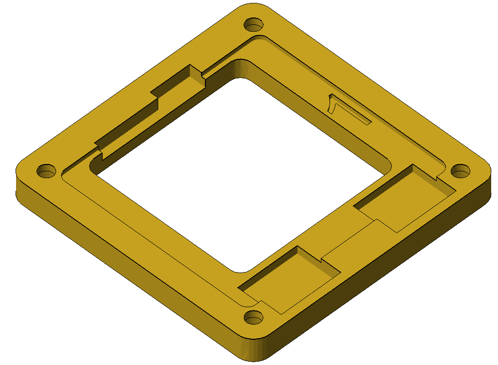
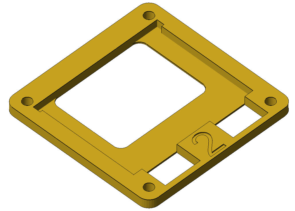
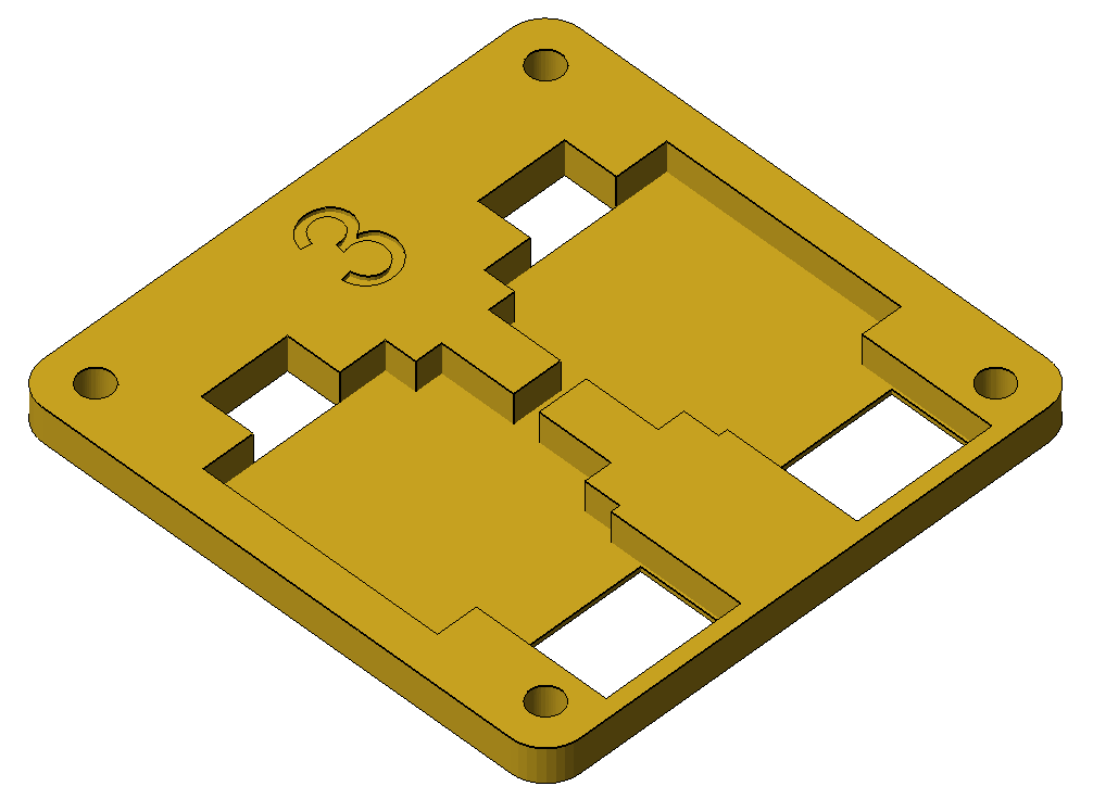
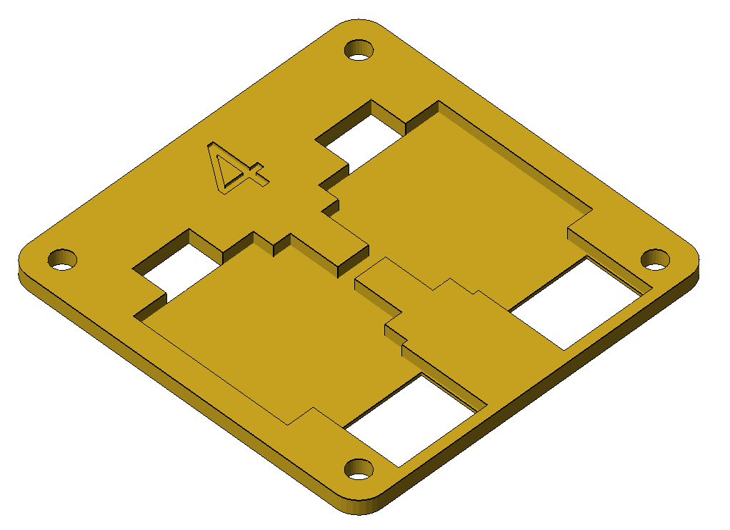
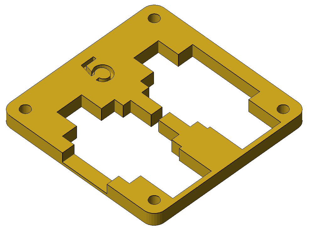
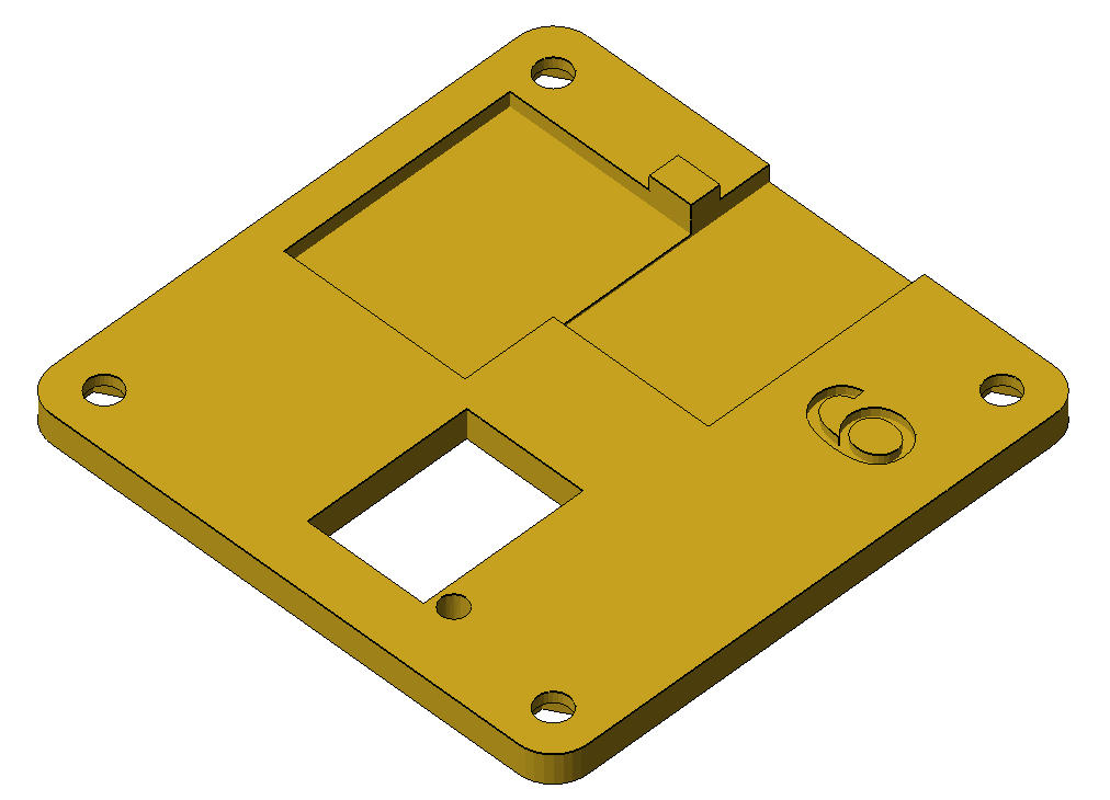
Let’s start with the 3D printed case. The modules are kept inside six different hard layers overlapped to form a small box, which is inserted in a rubber container shaped to rest on your wrist or on a belt. This type of case is very though so it's suitable for children making sports and other similar circumstances.
You can download here the six 3D parts to be printed.
|
|
|
|
|
|
- Inner Robust Layer 01: https://github.com/opencarecc/inpe/blob/master/3Dmodels/inpe_%20inner%20case%2001.stl
- Inner Robust Layer 02: https://github.com/opencarecc/inpe/blob/master/3Dmodels/inpe_%20inner%20case%2002.stl
- Inner Robust Layer 03: https://github.com/opencarecc/inpe/blob/master/3Dmodels/inpe_%20inner%20case%2003.stl
- Inner Robust Layer 04: https://github.com/opencarecc/inpe/blob/master/3Dmodels/inpe_%20inner%20case%2004.stl
- Inner Robust Layer 05: https://github.com/opencarecc/inpe/blob/master/3Dmodels/inpe_%20inner%20case%2005.stl
- Inner Robust Layer 06: https://github.com/opencarecc/inpe/blob/master/3Dmodels/inpe_%20inner%20case%2006.stl
Look at this image to have a full visual of the six layers, for each one is pointed out the front and the rear face.
You can see here a 3D view of the stacking order. Note also the name of the modules which have to be placed in each layer.
To better understand how to insert the RePhone parts inside the six 3D printed layers, and how to connect them, look at the following schematics. Note that schematic is made by two parts, one for each side of the case.

|

|
Indeed from the main module two different set of cables exit, and to each cable you have to connect some modules. These modules can be housed in the layers' recesses, with cables which pass through holes.
 
|
 
|
here is the prototype printed with red filament, of course you can choose a different material and color.
 
|
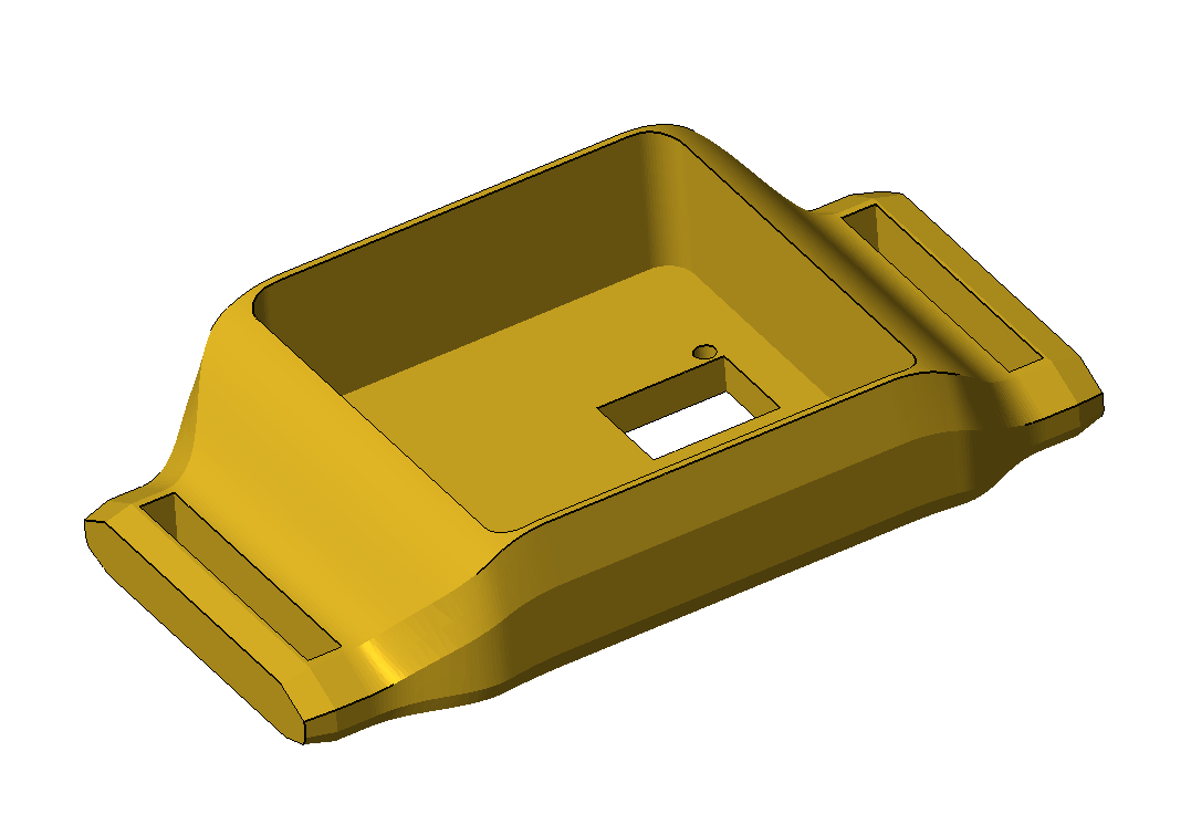
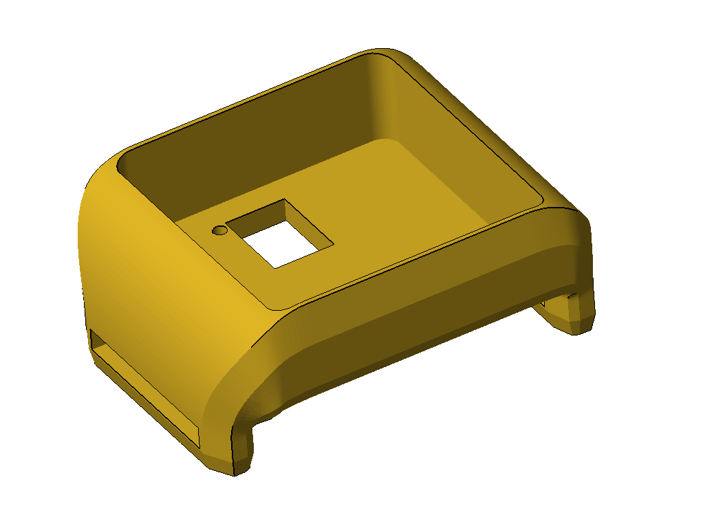
The external case is made with a special material. It's a rubber 3D printer filament, and you need some special skill to use it to make this 3D model, ask to someone for advices if it's your first time. You can choose between two similar cases, one more suitable for coupling with wrist, other more appropriate for flat surfaces. Click on images to download correspondent 3D Model.
|
Links to 3D models are also here:
- Outer case 01: https://github.com/opencarecc/inpe/blob/master/3Dmodels/inpe_%20outer%20case%2001.stl
- Outer case 02: https://github.com/opencarecc/inpe/blob/master/3Dmodels/inpe_%20outer%20case%2002.stl
Print the piece in your 3D printer or go to your nearest Makerspace.

Once you insert parts inside, your device should appear like this picture.
Use a simple fabric band as bracelet, maybe a fabric wristband from a wristwatch.
The soft wrist case is made from the same rubber filament of the shell you saw before, and housed on a leather layer. Download here the 3D model and the dxf file of the leather piece. Here is an image of the model.

Hereafter the parts attached together and some main components inserted.

In the picture below a 3D printer is making the model.

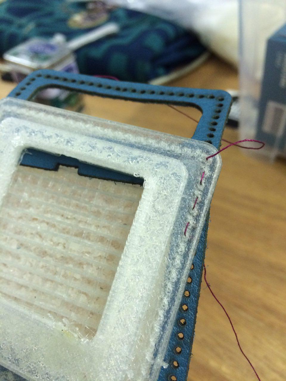
To attach shells together you can use both a simple stitching or some studs.
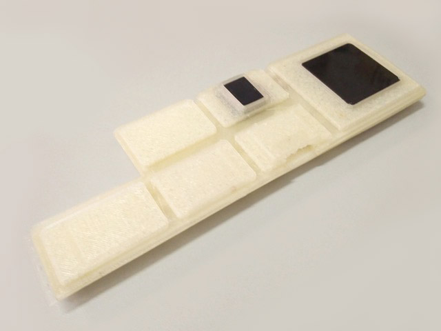
Then you need a wristband to contain the rubber shell with modules inside. Wristband is made froma leather sheet, cut with laser machine. Here is the .dxf file with the shape and holes to sewing: https://raw.githubusercontent.com/opencarecc/inpe/master/3Dmodels/IpEWristwatch.dxf.
The cut leather out of the laser machine is like this:
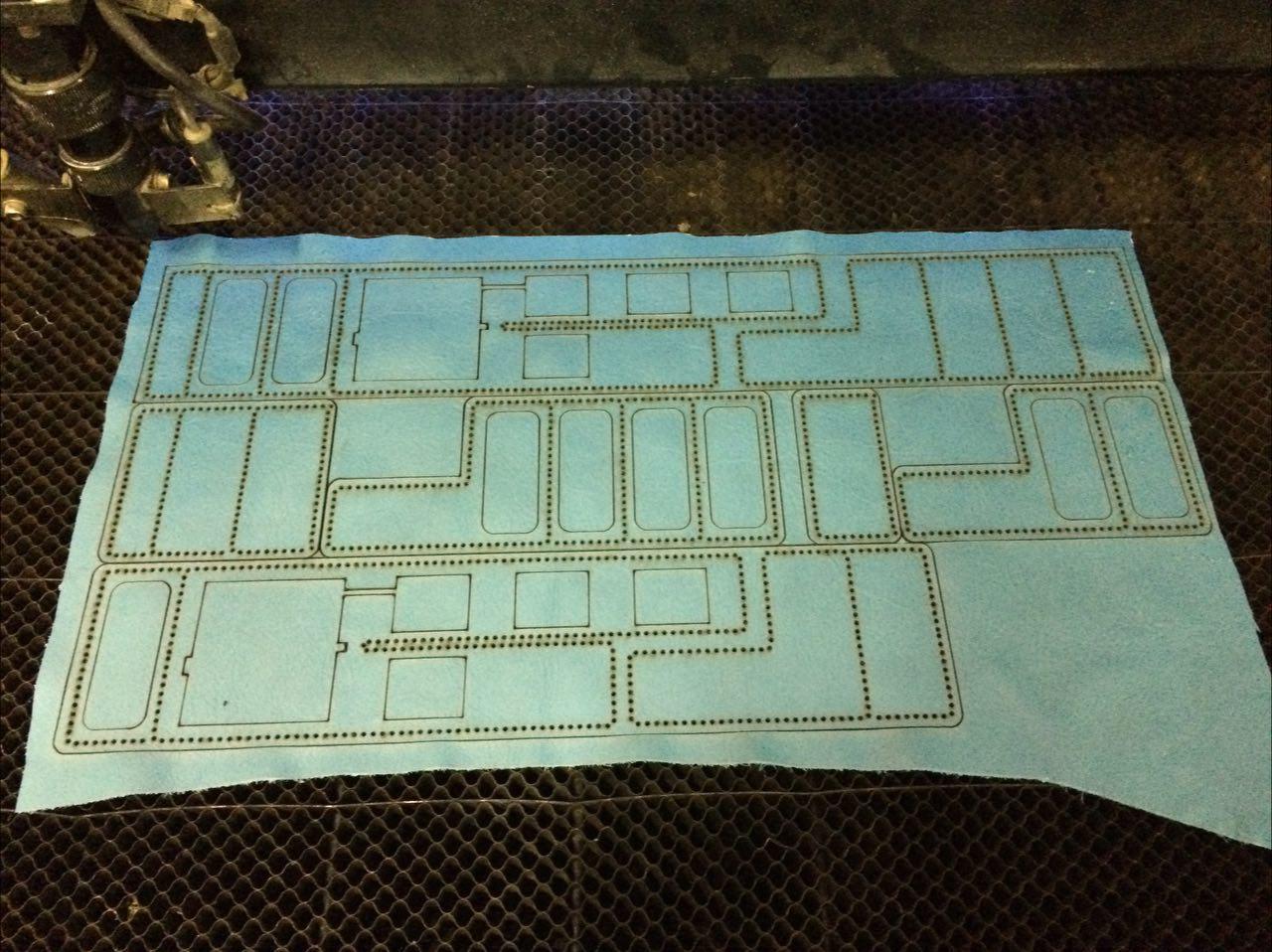
And sewing it to the rubber parts,
You obtain so a good solution to keep your device on wrist or arm.
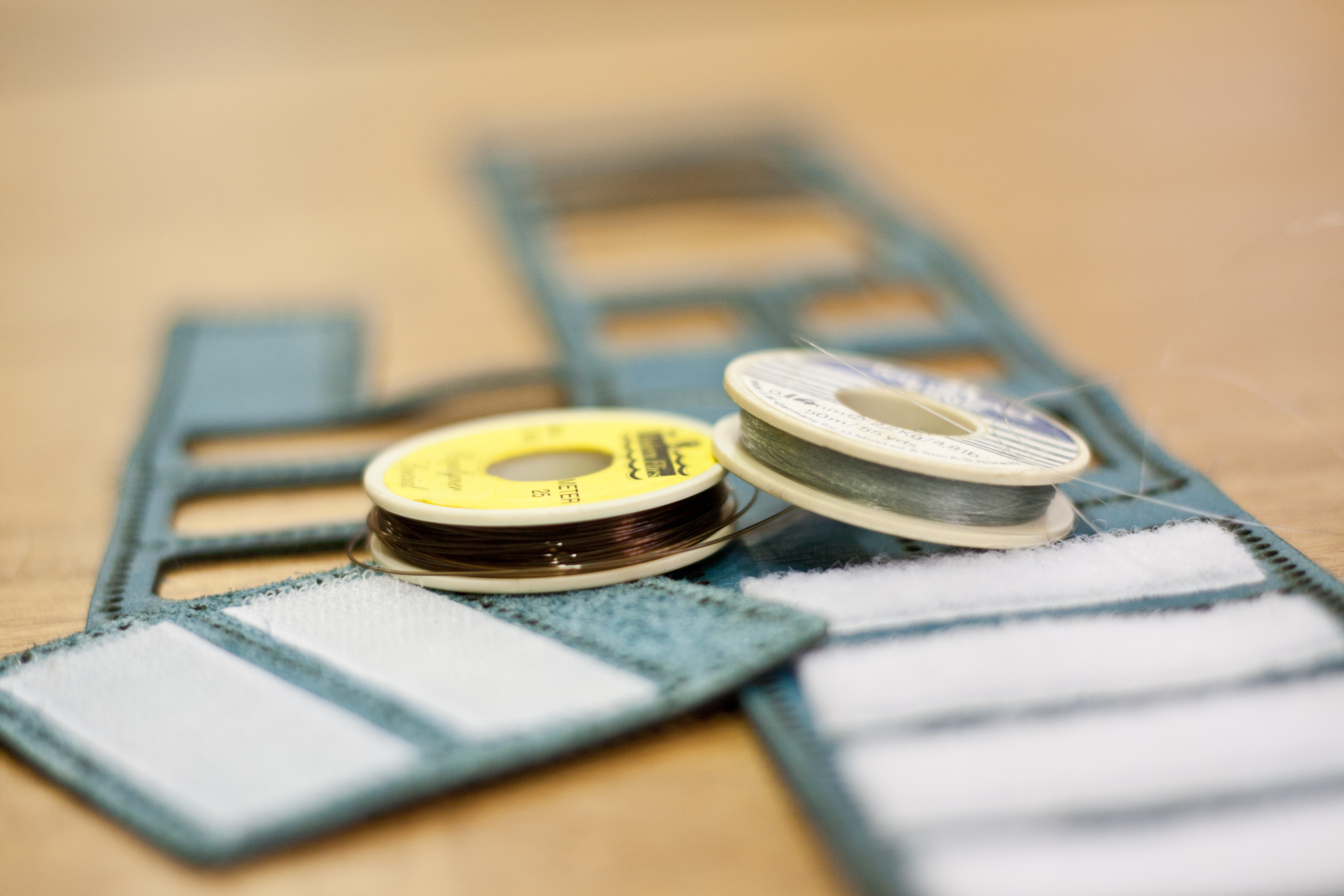
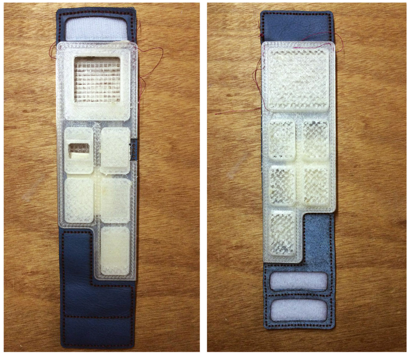
Now insert modules and connect the battery.
If you have already uploaded the software, you only need to connect the USB cable to charge battery.
To set up parameters and telephone number you can use the InPe touchscreen. Follow the simple instructions on the screen, then feel free to start your day with InPe protection.


